

Question: Consider a simple von Neumann architecture computer like the one discussed in Section 3.3.1 and depicted in Figure 3.34. One of its machine language instructions
Consider a simple von Neumann architecture computer like the one discussed in Section 3.3.1 and depicted in Figure 3.34. One of its machine language instructions is an ANDM instruction that reads the contents of a memory location (specified by direct addressing), bitwise ANDs this data with the contents of a specified CPU register, then stores the result back in that same register. List and describe the sequence of steps that would have to be carried out under the supervision of the processor’s control unit in order to implement this instruction.
Section 3.3.1
In order to appreciate the features of machine ISAs, it is important to realize what a computer program is. You may think of it as a C, C++, Fortran, or Java listing, but all that high-level syntax is left behind in producing an executable file. In the end, regardless of how it was originally specified, a computer program is a sequence of binary machine language instructions to be performed in order (that order, of course, often being alterable based on the outcome of tests performed and decisions made while the program is running). Each machine language instruction is no more and no less than a collection of bits that are decoded by logic inside the processor’s control unit; each combination of bits has a unique meaning to the control unit, telling it to perform an operation on some item of data, move data from one place to another, input or output data from or to a device, alter the flow of program execution, or carry out some other task that the machine’s hardware is capable of doing.
Machine language instructions may be fixed or variable in length and are normally divided into “fields,” or groups of bits, each of which is decoded to tell the control unit about a particular aspect of the instruction.
A simple machine might have 16-bit instructions divided into, for example, five fields as shown in Figure 3.2. (This example is taken from the instruction set of DEC’s PDP-11 minicomputer of the early 1970s.)
The first set of bits comprise the operation code field (op code for short).
They define the operation to be carried out. In this case, because there are four op code bits, the computer can have at most 24 = 16 instructions (assuming this is the only instruction format). The control unit would use a 4 to 16 decoder to uniquely identify which operation to perform based on the op code for a particular instruction.
The remaining 12 bits specify two operands to be used with the instruction. Each operand is identified by two three-bit fields: one to specify a register and one to specify an addressing mode (or way of determining the operand’s location given the contents of the register in question).
Having three bits to specify a register means that the CPU is limited to having only 23 = 8 internal registers (or, at least, that only eight can be used for the purpose of addressing operands). Likewise, allocating three bits to identify an addressing mode means there can be no more than eight such modes. One of them might be register direct, meaning the operand is in the specified register; another might be register indirect, meaning the register contains not the operand itself but a pointer to the operand in memory. (We will examine addressing modes more thoroughly in Section 3.1.3.) Each of the three-bit fields will be interpreted by a 3 to 8 decoder, the outputs of which will be used by the control unit in the process of determining the locations of the operands so that they can be accessed. Thus, within the 16 bits of the instruction, the CPU finds all the information it needs to determine what it is to do next.
A machine may have one or several formats for machine language instructions. (A processor with variable-length instructions will have multiple machine language formats, but there may also be multiple formats for a given instruction size. Oracle’s SPARC architecture, for example, has three 32-bit instruction formats.) Each format may have different-sized bit fields and have different meanings for the fields. Figure 3.3 shows an example of an architecture that has fixed-length, 32-bit instructions with three formats. Notice how the two leftmost bits are used to identify the format of the remaining 30 bits. This would correspond to a two-level decoding scheme in which the outputs of a 2 to 4 decoder driven by the two format bits would determine which set of secondary decoders would be used to interpret the remaining bits. This type of arrangement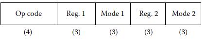
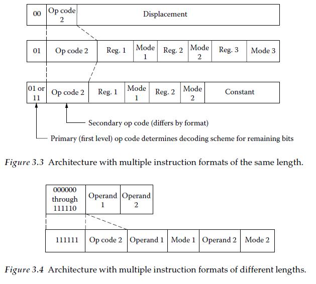
makes the control unit a little more complex but allows the machine to have a greater variety of instructions than would be possible with just one instruction format.
Because the types of instructions and number of operands required for each sometimes vary considerably, it is often more space-efficient to encode some types of instructions in fewer bits while others take up more bits. Having instructions of variable lengths complicates the process of fetching and decoding instructions (the first two steps in the von Neumann execution cycle; see Figure 1.2) but may be justified if keeping executable code size small is important. Figure 3.4 shows an example of an instruction set with some 16-bit instructions and some 32-bit instructions.
One particular op code (111111) from the shorter format is used to tell the CPU that the next 16 bits are to be interpreted as the second part of the current instruction, rather than the next instruction.
Figure 3.34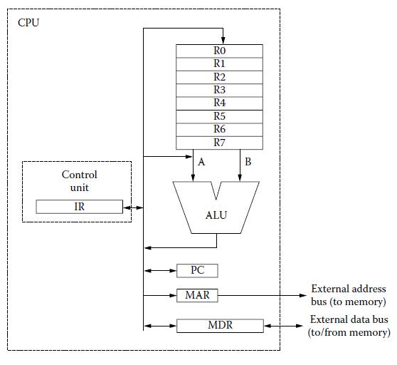
Op code (4) Reg. 1 (3) Mode 1 (3) Reg. 2 (3) Mode 2 (3)
Step by Step Solution
3.38 Rating (160 Votes )
There are 3 Steps involved in it
To implement an ANDM instruction on a simple von Neumann architecture computer the processors control unit will execute a series of steps to complete ... View full answer

Get step-by-step solutions from verified subject matter experts