

The circuit in Figure P2.49 consists of four JK flip-flops. Inputs J and K are not shown,
Question:
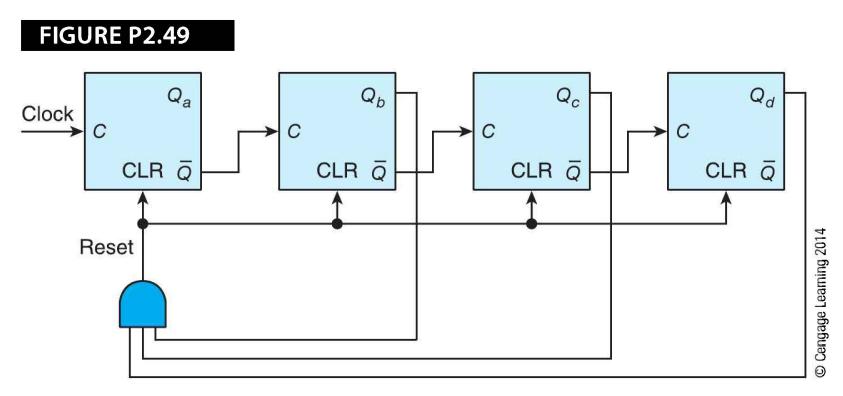
The circuit in Figure P2.49 consists of four JK flip-flops. Inputs J and K are not shown, because it is assumed that they are both permanently connected to a logical 1. These JK flip-flops are positive edge-triggered (i.e., they change state on the rising edge of the clock). Note that these flip-flops have a CLR ( clear) input that sets Q to 1 when CLR = 1. What does this circuit do?
Fantastic news! We've Found the answer you've been seeking!
Step by Step Answer:
The problem can be solved with a simple timing diagram However we can ...View the full answer

Answered By
Amjad Mahmood
I am a self motivated person with passion in giving academic assistance. I have vast tutoring experience of more than 5 years and my primary objective as a tutor is to ensure that a student achieves their academic goals.
0 Reviews
10+ Question Solved
Related Book For 

Computer Organization And Architecture Themes And Variations
ISBN: 9781111987046
1st Edition
Authors: Alan Clements
Question Posted:
