

The state diagram in Figure P2.51 describes a system with states A, B, and C. The system
Question:
The state diagram in Figure P2.51 describes a system with states A, B, and C. The system is initialized in State A. The state transition notation x/yz indicates that an input x causes a transition in the direction shown and the system outputs the value yz. For example, an input 1 in State A causes a transition to State B, and the system outputs 01.
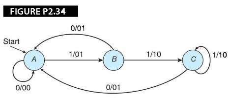
(a) How many flip-flops would be required to construct this system?
(b) If the system receives the input 00010011001010111110010, what would the output be?
Fantastic news! We've Found the answer you've been seeking!
Step by Step Answer:
a This system has three states and requires two flipflops which can store up to four ...View the full answer

Answered By
Muhammad Umair
I have done job as Embedded System Engineer for just four months but after it i have decided to open my own lab and to work on projects that i can launch my own product in market. I work on different softwares like Proteus, Mikroc to program Embedded Systems. My basic work is on Embedded Systems. I have skills in Autocad, Proteus, C++, C programming and i love to share these skills to other to enhance my knowledge too.
1+ Reviews
10+ Question Solved
Related Book For 

Computer Organization And Architecture Themes And Variations
ISBN: 9781111987046
1st Edition
Authors: Alan Clements
Question Posted:
