

Question: The transformer connections are shown in Fig. 6. The A-Y transformers between buses 3 and 5 is grounded through a reactor of reactance 0.10
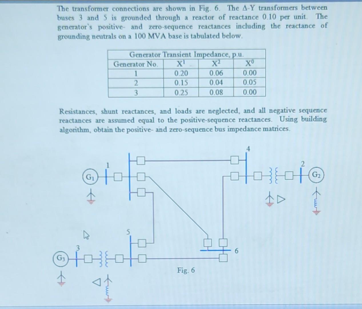
The transformer connections are shown in Fig. 6. The A-Y transformers between buses 3 and 5 is grounded through a reactor of reactance 0.10 per unit. The generator's positive and zero-sequence reactances including the reactance of grounding neutrals on a 100 MVA base is tabulated below. G (G3 Alli otto Resistances, shunt reactances, and loads are neglected, and all negative sequence reactances are assumed equal to the positive-sequence reactances. Using building algorithm, obtain the positive and zero-sequence bus impedance matrices. Generator Transient Impedance, p.u. X 0.20 0.15 0.25 Generator No. Fu 2 3 0.06 0.04 0.08 Fig. 6 0.00 0.05 0.00 FOTOT 6 Alli A G funt
Step by Step Solution
There are 3 Steps involved in it
Answer First we need to calculate the Thevenin equivalent impedance for each g... View full answer

Get step-by-step solutions from verified subject matter experts