

Question: A process is simulated by the second-order passive circuit, shown in Figure P5.52, where the feedback amplifier, controller, and final control element are represented by
A process is simulated by the second-order passive circuit, shown in Figure P5.52, where the feedback amplifier, controller, and final control element are represented by op-amp circuits.
a. Denoting the input and output as R(s) = Vi (s) and C(s) = Vo(s), with R(s) - C(s) = E(s), and noting that the feedback amplifier has a unity gain, draw a block diagram for this feedback control system, where GC(s), GF(s), and GP(s) are the transfer functions of the controller, final control element, and the process, respectively.
b. Find the value of RP that makes the circuit representing the process critically damped.
c. Noting that the proportional controller is simply an amplifier, GC(s) = KP, find the value of its gain KP that results in dominant closed-loop poles with a damping ratio, ζ = 0:5, and a settling time, Ts = 4 ms. Verify that the other pole is non dominant. What would be the appropriate value of the controller potentiometer, RF, given that its tolerance is ±10%?
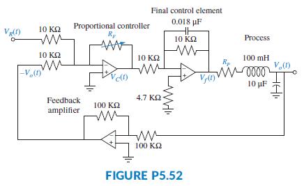
Final control element 0.018 pF 10 K2 Proportional controller 10 KQ Process 10 KQ 10 K2 100 mH V,) Vel) 10 F 4.7 K2 Feedback 100 K2 amplifier 100 K2 FIGURE P5.52
Step by Step Solution
3.44 Rating (179 Votes )
There are 3 Steps involved in it

Get step-by-step solutions from verified subject matter experts