

Assume ideal operational amplifiers in the circuit of Figure P5.50. a. Show that the leftmost operational amplifier
Question:
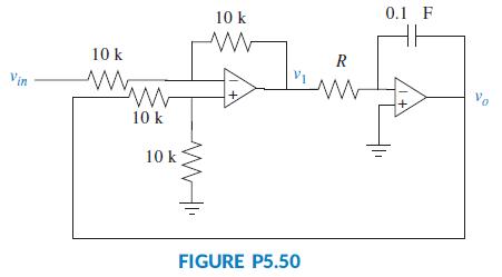
Assume ideal operational amplifiers in the circuit of Figure P5.50.
a. Show that the leftmost operational amplifier works as a subtracting amplifier. Namely, v1 = vo - vin.
b. Draw a block diagram of the system, with the subtracting amplifier represented with a summing junction, and the circuit of the rightmost operational amplifier with a transfer function in the forward path. Keep R as a variable.
c. Obtain the system’s closed-loop transfer function.
d. For a unit step input, obtain the value of R that will result in a settling time Ts = 1 msec.
e. Using the value of R calculated in Part d, make a sketch of the resulting unit step response.
Step by Step Answer:

This question has not been answered yet.
You can Ask your question!
Related Book For 
Question Posted:
