

Figure P4.9 shows five step responses of an automatic voltage regulation system as one of the system
Question:
Figure P4.9 shows five step responses of an automatic voltage regulation system as one of the system parameters varies (Gozde, 2011). Assume for all five responses that they are those of a second order system with an overshoot of 20%. Make a sketch of the positions of the poles in the complex plane for each one of the responses. Label the curves A through E from left to right.
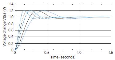
FIGURE P4.9 Time responses for an automatic voltage regulation system
Fantastic news! We've Found the answer you've been seeking!
Step by Step Answer:
For a second order system with an overshoot of 20 the poles of the system are complex con...View the full answer

Answered By
Muhammad Raffay Khanzada
Hi! I am Raffay. I am twenty two years old. I did my matriculation with a major in science. Then I completed my college studies majoring in engineering. Now I am studying business studies at Iqra University (last semester). I also have a diploma in English grammar. I have work experience in jobs and internships also.
0 Reviews
10+ Question Solved
Related Book For 
Question Posted:
