

Question: Figure P9.5 shows a two-tank system. The liquid inflow to the upper tank can be controlled using a valve and is represented by F 0
Figure P9.5 shows a two-tank system. The liquid inflow to the upper tank can be controlled using a valve and is represented by F0. The upper tank’s outflow equals the lower tank’s inflow and is represented by F1. The outflow of the lower tank is F2. The objective of the design is to control the liquid level, y(t), in the lower tank. The open-loop transmission for this system is Y(s)/Fo(s) = a2a3/s2 + (a1 + a4)s + a1a4 (Romagnoli, 2006). The system will be controlled in a loop analogous to that of Figure P9.1, where the lower liquid level will be measured and compared to a set point. The resulting error will be fed to a controller, which in turn will open or close the valve feeding the upper tank.
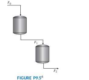
a. Assuming a1 = 0.04; a2 = 0.0187; a3 = 1; and a4 = 0.227, design a lag compensator to obtain a step response steady-state error of 10% without affecting the system’s transient response appreciably.
b. Verify your design through MATLAB simulations.
Fo F1 F2 FIGURE P9,56
Step by Step Solution
3.32 Rating (167 Votes )
There are 3 Steps involved in it

Get step-by-step solutions from verified subject matter experts