

Question: The INTEST instruction (code 010) allows testing of the core logic by shifting test data into the boundary scan register (BSR1) and then updating BSR2
(a) Referring to Figure 10-16, give the sequence for TMS and TDI that will load the instruction register with 010 and BSR2 with 011. In addition, give the state sequence, starting in state 0.
(b) In the code of Figure 10-21, what changes or additions must be made in the last BSRout assignment statement, in the CaptureDR state, and in the UpdateDR state to implement the INTEST instruction?
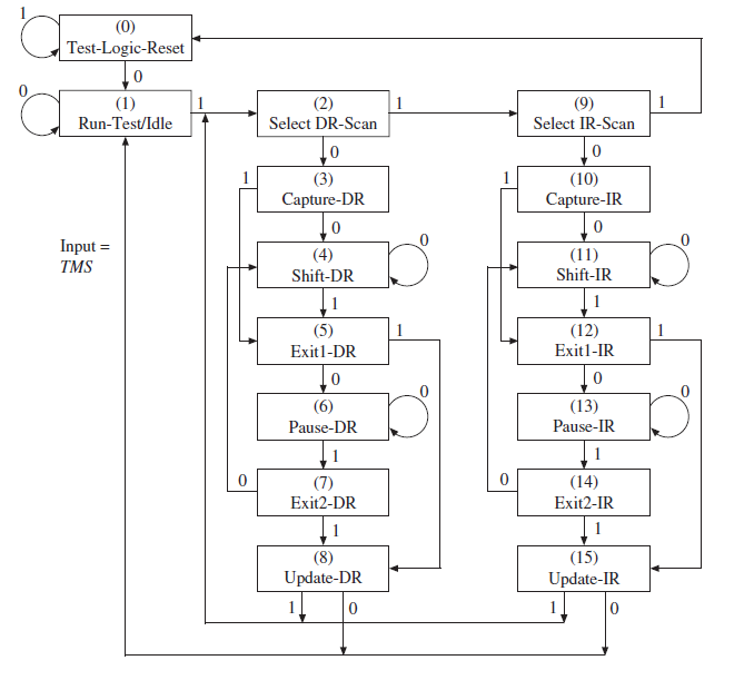
Figure 10-16: State Machine for TAP Controller
(0) Test-Logic-Reset 1 (1) (2) (9) Run-Test/Idle Select DR-Scan Select IR-Scan (10) Capture-IR (3) Capture-DR Input = TMS (4) Shift-DR (11) Shift-IR 1 (5) Exitl-DR (12) Exitl-IR (6) (13) Pause-IR Pause-DR [ 1 (7) (14) Exit2-DR Exit2-IR (15) Update-IR (8) Update-DR 1
Step by Step Solution
3.43 Rating (166 Votes )
There are 3 Steps involved in it
a b Changes to code CaptureDR state insert after IDR 001 or IDR ... View full answer

Get step-by-step solutions from verified subject matter experts