

Question: The next-state equations for a sequential circuit with two flip-flops (Q 1 and Q 2 ), input signals R, S, T, and an output P
The next-state equations for a sequential circuit with two flip-flops (Q1and Q2), input signals R, S, T, and an output P are
D1 = Q1+ = Q2R1 Q1S
D2 = Q2+ = Q1+ Q2'T
The output equation is P = Q2RT + Q1ST
(a) Explain how this sequential circuit can be implemented using a single Figure 6-3 logic block. Write the equation that each function generator in the block will implement.
(b) Mark (highlight) the input signals, the state and output variables, and the activated paths on a copy of Figure 6-3.
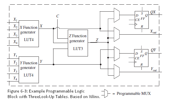
| X1 | QX CE FF X2X Function X generator | X3 | X4 Z Function LUT4 generator LUT3 QY | Y | Y2 Y Function | FF CE generator Y3 Y out LUT4 Y4 Figure 6-3: Example Programmable Logic Block with Threelook-Up Tables. Based on Xilinx. Programmable MUX
Step by Step Solution
3.36 Rating (168 Votes )
There are 3 Steps involved in it
a The next state equation of Q 1 can be implemented u... View full answer

Get step-by-step solutions from verified subject matter experts