

a. For the situation depicted in Figure 3-6, determine the waveform at the OR gate output. Figure
Question:
a. For the situation depicted in Figure 3-6, determine the waveform at the OR gate output.
Figure 3-6
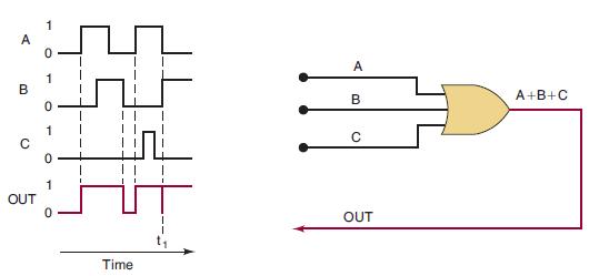
b. What would happen to the glitch in the output in Figure 3-6 if input C sat in the HIGH state while A and B were changing at time t1?
Figure 3-6
Fantastic news! We've Found the answer you've been seeking!
Step by Step Answer:
a The three OR gate inputs A B and C are varying as shown by their waveform diagrams The OR gate out...View the full answer

Answered By
Branice Buyengo Ajevi
I have been teaching for the last 5 years which has strengthened my interaction with students of different level.
1+ Reviews
10+ Question Solved
Related Book For 

Digital Systems Principles And Application
ISBN: 9780134220130
12th Edition
Authors: Ronald Tocci, Neal Widmer, Gregory Moss
Question Posted:
