

Question: A technician breadboards a logic circuit for testing. As she tests the circuits operation, she finds that many of the FFs and counters are triggering
A technician breadboards a logic circuit for testing. As she tests the circuit’s operation, she finds that many of the FFs and counters are triggering erratically. Like any good technician, she checks the VCC line with a DC meter and reads 4.97 V, which is acceptable for TTL. She then checks all circuit wiring and replaces each IC one by one, but the problem persists. Finally she decides to observe VCC on the scope and sees the waveform shown in Figure 8-57. What is the probable cause of the noise on VCC? What did the technician forget to include when she breadboarded the circuit?
Figure 8-57
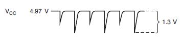
Vcc 1 4.97 V 1.3 V
Step by Step Solution
3.48 Rating (161 Votes )
There are 3 Steps involved in it
The probable cause of the noise on VCC is highfrequency switching currents When digital ICs switch s... View full answer

Get step-by-step solutions from verified subject matter experts