

A technician tests the circuit of Figure 5-13 and records the observations shown in Table 5-1. He
Question:
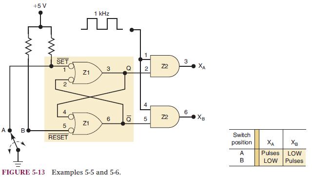
A technician tests the circuit of Figure 5-13 and records the observations shown in Table 5-1. He notices that when the switch is in position B, the circuit functions correctly, but in position A the latch does not set to the Q = 1 state. What are the possible faults that could produce this malfunction?
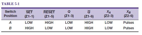
Figure 5-13
Fantastic news! We've Found the answer you've been seeking!
Step by Step Answer:
There are several possibilities 1 An internal open connection at Z11 which would prevent Q from ...View the full answer

Answered By
Leah Muchiri
I am graduate in Bachelor of Actuarial Science and a certified accountant. I am also a prolific writer with six years experience in academic writing. My working principle are being timely and delivering 100% plagiarized free work. I usually present a precised solution to every work am assigned to do. Most of my student earn A++ GRADE using my precised and correct solutions.
52+ Reviews
125+ Question Solved
Related Book For 

Digital Systems Principles And Application
ISBN: 9780134220130
12th Edition
Authors: Ronald Tocci, Neal Widmer, Gregory Moss
Question Posted:
