

Assume a 1-Hz clock is applied to the seconds stage of the clock in Figure 10-17. The
Question:
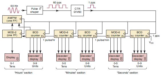
Assume a 1-Hz clock is applied to the seconds stage of the clock in Figure 10-17. The MOD-10 units of seconds counter’s terminal count (tc) output is shown in Figure 10-51. Draw a similar diagram showing the number of clock cycles between the tc output pulses of each of the following:
(a) Tens of seconds counter
(b) Units of minutes counter
(c) Tens of minutes counter
Figure 10-51
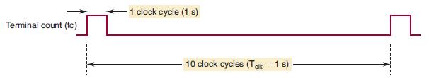
Figure 10-17
Step by Step Answer:

This question has not been answered yet.
You can Ask your question!
Related Book For 

Digital Systems Principles And Application
ISBN: 9780134220130
12th Edition
Authors: Ronald Tocci, Neal Widmer, Gregory Moss
Question Posted:
