

Question: Figure 12-41 shows a simple circuit for manually programming a 2732 EPROM. Each EPROM data pin is connected to a switch that can be set
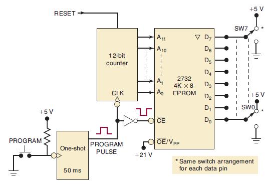
Figure 12-41 shows a simple circuit for manually programming a 2732 EPROM. Each EPROM data pin is connected to a switch that can be set at a 1 or a 0 level. The address inputs are driven by a 12-bit counter. The 50-ms programming pulse comes from a one-shot each time the PROGRAM push button is actuated.
(a) Explain how this circuit can be used to program the EPROM memory locations sequentially with the desired data.
(b) Show how 74293s and a 74121 can be used to implement this circuit.
(c) Should switch bounce have any effect on the circuit operation?
Figure 12-41
+5V PROGRAM RESET One-shot 50 ms 12-bit counter CLK PROGRAM PULSE I +21 V A11 A 10 1 A CE V D De D5 D4 D3 D D 2732 4K X 8 EPROM OE/V PP SW7 +5 V 1+5V I SWO *Same switch arrangement for each data pin
Step by Step Solution
3.44 Rating (151 Votes )
There are 3 Steps involved in it

Get step-by-step solutions from verified subject matter experts