

Figure 4-71 shows a BCD counter that produces a four-bit output representing the BCD code for the
Question:
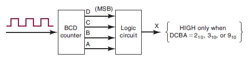
Figure 4-71 shows a BCD counter that produces a four-bit output representing the BCD code for the number of pulses that have been applied to the counter input. For example, after four pulses have occurred, the counter outputs are DCBA = 01002 = 410. The counter resets to 0000 on the tenth pulse and starts counting over again. In other words, the DCBA outputs will never represent a number greater than 10012 = 910.
(a)* Design the logic circuit that produces a HIGH output whenever the count is 2, 3, or 9. Use K mapping and take advantage of the don’t-care conditions.
(b) Repeat for x = 1 when DCBA = 3, 4, 5, 8.
Figure 4-71
Fantastic news! We've Found the answer you've been seeking!
Step by Step Answer:

Answered By
Gilbert Chesire
I am a diligent writer who understands the writing conventions used in the industry and with the expertise to produce high quality papers at all times. I love to write plagiarism free work with which the grammar flows perfectly. I write both academics and articles with a lot of enthusiasm. I am always determined to put the interests of my customers before mine so as to build a cohesive environment where we can benefit from each other. I value all my clients and I pay them back by delivering the quality of work they yearn to get.
14+ Reviews
49+ Question Solved
Related Book For 

Digital Systems Principles And Application
ISBN: 9780134220130
12th Edition
Authors: Ronald Tocci, Neal Widmer, Gregory Moss
Question Posted:
