

Figure 4-77 shows the intersection of a main highway with a secondary access road. Vehicle-detection sensors are
Question:
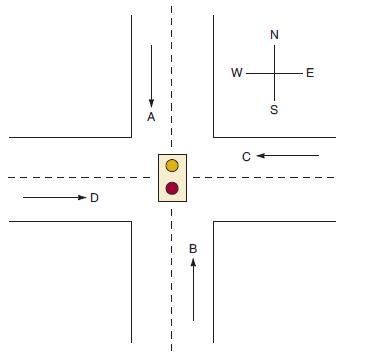
Figure 4-77 shows the intersection of a main highway with a secondary access road. Vehicle-detection sensors are placed along lanes C and D (main road) and lanes A and B (access road). These sensor outputs are LOW (0) when no vehicle is present and HIGH (1) when a vehicle is present. The intersection traffic light is to be controlled according to the following logic:
1. The east-west (E-W) traffic light will be green whenever both lanes C and D are occupied.
2. The E-W light will be green whenever either C or D is occupied but lanes A and B are not both occupied.
3. The north-south (N-S) light will be green whenever both lanes A and B are occupied but C and D are not both occupied.
4. The N-S light will also be green when either A or B is occupied while C and D are both vacant.
5. The E-W light will be green when no vehicles are present.
Using the sensor outputs A, B, C, and D as inputs, design a logic circuit to control the traffic light. There should be two outputs, N-S and E-W, that go HIGH when the corresponding light is to be green. Simplify the circuit as much as possible and show all steps.
Figure 4-77
Step by Step Answer:
To design the logic circuit for controlling the traffic light based on the given conditions we can u...View the full answer


Digital Systems Principles And Application
ISBN: 9780134220130
12th Edition
Authors: Ronald Tocci, Neal Widmer, Gregory Moss
