

Question: Figure 9-73 shows how a decoder can be used in the generation of control signals. Assume that a RESET pulse has occurred at time t
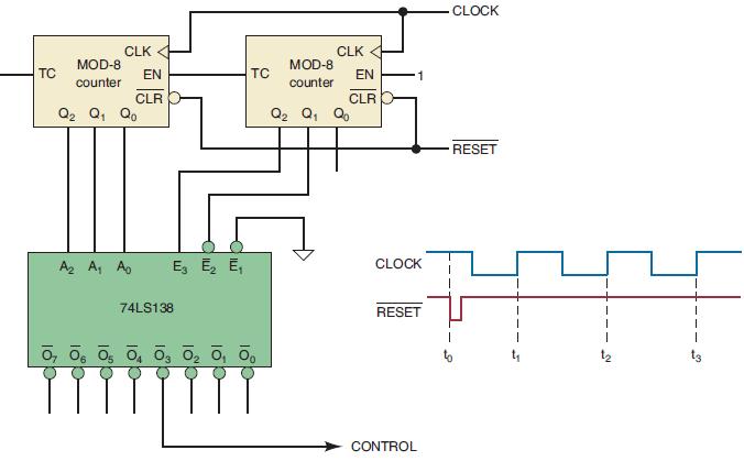
Figure 9-73 shows how a decoder can be used in the generation of control signals. Assume that a RESET pulse has occurred at time t0, and determine the CONTROL waveform for 32 clock pulses.
Figure 9-73
TC MOD-8 counter CLK EN CLR Q Q Qo A A Ap 74LS138 E E E TC 07 06 05 04 03 0 0 00 MOD-8 counter CLK EN CLR Q Q Qo 1 CLOCK RESET CONTROL CLOCK RESET
Step by Step Solution
★★★★★
3.37 Rating (169 Votes )
There are 3 Steps involved in it
1 Expert Approved Answer
Step: 1 Unlock

To determine the CONTROL waveform for 32 clock pulses in Figure 973 we can use ... View full answer
Question Has Been Solved by an Expert!
Get step-by-step solutions from verified subject matter experts
Step: 2 Unlock
Step: 3 Unlock