

Question: Simulate the universal shift-register design from Example 7-27. Data from Example 7-27 Suppose we want to design a universal four-bit shift register, using HDL, that
Simulate the universal shift-register design from Example 7-27.
Data from Example 7-27
Suppose we want to design a universal four-bit shift register, using HDL, that has four synchronous modes of operation: Hold Data, Shift Left, Shift Right, and Parallel Load. Two input bits will select the operation that is to be performed on each rising edge of the clock. To implement a shift register, we can use structural code to describe a string of flip-flops. Making the shift register versatile by allowing it to shift right or left or to parallel load would make this file quite long and thus hard to read and understand using structural methods. A much better approach is to use the more abstract and intuitive methods available in HDL to describe the circuit concisely. To do this, we must develop a strategy that will create the shifting action. The concept is very similar to the one presented in Example 7-18, where a D flip-flop register chip (74174) was wired to form a shift register. Rather than thinking of the shift register as a serial string of flip-flops, we consider it as a parallel register whose contents are being transferred in parallel to a set of bits that is offset by one bit position. Figure 7-83 demonstrates the concept of each transfer needed in this design.
Data from Example 7-18
Show how to connect the 74ALS174 so that it operates as a serial shift register with data shifting on each PGT of CP as follows: Serial input → Q5 → Q4 → Q3 → Q2 → Q1 → Q0. In other words, serial data will enter at D5 and will output at Q0.
Figure 7-83
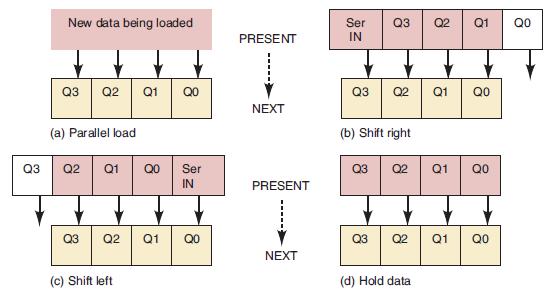
New data being loaded Q3 Q2 Q1 (a) Parallel load Q3 Q2 Q1 8 Q3 Q2 Q1 QO Ser IN (c) Shift left QO 8 QO PRESENT NEXT PRESENT NEXT Ser Q3 Q2 Q1 IN Q3 Q2 (b) Shift right Q3 Q2 Q3 Q2 (d) Hold data Q1 8 Q1 QO Q1 QO 8 QO 8 Qo
Step by Step Solution
3.37 Rating (172 Votes )
There are 3 Steps involved in it

Get step-by-step solutions from verified subject matter experts