

The synchronous data transmission system of Figure 9-32 and Figure 9-33 is malfunctioning. An oscilloscope is used
Question:
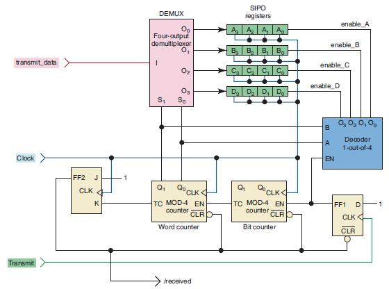
The synchronous data transmission system of Figure 9-32 and Figure 9-33 is malfunctioning. An oscilloscope is used to monitor the MUX and DEMUX outputs during the transmission cycle, with the results shown in Figure 9-82. What are the possible causes of the malfunction?
Figure 9-82
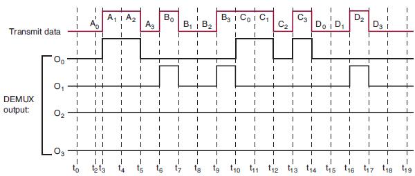
Figure 9-32
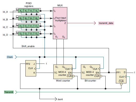
Figure 9-33
Fantastic news! We've Found the answer you've been seeking!
Step by Step Answer:

Answered By
Allan Simiyu
I am an adroit Writer. I am a dedicated writer having worked as a writer for 3 years now. With this, I am sure to ace in the field by helping students break down abstract concepts into simpler ideas.
8+ Reviews
54+ Question Solved
Related Book For 

Digital Systems Principles And Application
ISBN: 9780134220130
12th Edition
Authors: Ronald Tocci, Neal Widmer, Gregory Moss
Question Posted:
