

Question: What would a logic probe indicate at pin 13 and at pin 6 of Figure 4-37? Figure 4-37 74LS00 14 Voc 1 Open 13 3
What would a logic probe indicate at pin 13 and at pin 6 of Figure 4-37?
Figure 4-37
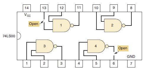
74LS00 14 Voc 1 Open 13 3 2 12 3 11 10 5 9 2 6 Open GND 7
Step by Step Solution
★★★★★
3.30 Rating (162 Votes )
There are 3 Steps involved in it
1 Expert Approved Answer
Step: 1 Unlock

Examination of the recorded results indicates that the INVERTER appears to be working properly but t... View full answer
Question Has Been Solved by an Expert!
Get step-by-step solutions from verified subject matter experts
Step: 2 Unlock
Step: 3 Unlock