

Question: 7. Showing Register Status Values The Tag register (Section 12.2.1) indicates the type of contents in each FPU register, using 2 bits for each (Fig.
7. Showing Register Status Values The Tag register (Section 12.2.1) indicates the type of contents in each FPU register, using 2 bits for each (Fig. 12-7). You can load the Tag word by calling the FSTENV instruction, which fills in the following protected-mode structure (defined in Irvine32.inc):
FPU_ENVIRON STRUCT controlWord WORD ?
ALIGN DWORD statusWord WORD ?
ALIGN DWORD tagWord WORD ?
ALIGN DWORD instrPointerOffset DWORD ?
instrPointerSelector DWORD ?
operandPointerOffset DWORD ?
operandPointerSelector WORD ?
WORD ? ; not used FPU_ENVIRON ENDS Write a program that pushes two or more values on the FPU stack, displays the stack by calling ShowFPUStack, displays the Tag value of each FPU data register, and displays the register number that corresponds to ST(0). (For the latter, call the FSTSW instruction to save the status word in a 16-bit integer variable, and extract the stack TOP indicator from bits 11 through 13.)
Use the following sample output as a guide:
------ FPU Stack ------
ST(0): +1.5000000E+000 ST(1): +2.0000000E+000 R0 is empty R1 is empty R2 is empty R3 is empty R4 is empty R5 is empty R6 is valid R7 is valid ST(0) = R6 From the sample output, we can see that ST(0) is R6, and therefore ST(1) is R7. Both contain valid floating-point numbers.
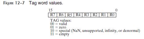
FIGURE 12-7 Tag word values. 15 R7 R6 R5 R4 | R3 | R2 | R1 RO TAG values: 00 = valid 01 10 zero special (NaN, unsupported, infinity, or denormal) 11 = empty
Step by Step Solution
There are 3 Steps involved in it

Get step-by-step solutions from verified subject matter experts