

Question: The circuit in Figure 11.12 provides an easily testable implementation of the FSM in Figure 6.76. In Example 11.3 we showed how this circuit may
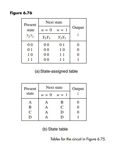
The circuit in Figure 11.12 provides an easily testable implementation of the FSM in Figure 6.76. In Example 11.3 we showed how this circuit may be tested by testing the combinational part using randomly chosen tests. A different approach to testing may be to attempt to determine whether the circuit actually realizes the functionality specified in the state table in Figure 6.76b. This can be done by making the circuit go through all transitions given in the state table. For example, after applying the Reset n = 0 signal, the circuit begins in state A. It must be verified that the circuit is indeed forced into state A by scanning out the expected valuation y2y1 = 00. Next each transition must be checked. To verify the transition A → A if w = 0, it is necessary to make the input w equal to 0 and allow the normal operation to take place for one clock cycle by making Normal/Scan = 0. The value of the output z must be observed. This is followed by scanning out the values of y2 and y1 to see if y2y1 = 00. At the same time, the valuation for the next test should be scanned in. If this test involves verifying that B → A if w = 0, then the valuation y2y1 = 01 is scanned in. This process continues until all transitions have been verified. Indicate in the form of a table the values of the signals Normal/Scan, Scan-in, Scan-out, w, and z, as well as the transition tested, for each clock cycle necessary to perform the complete test for this circuit.
Data from Example 11.3:
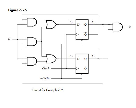
Figure 6.75 shows a circuit that recognizes a specific input sequence. The circuit can be made easily testable by modifying it for scan path as shown in Figure 11.12. The combinational part, consisting of four AND and two OR gates, is the same in both figures.
The flip-flops can be tested by scanning through them a sequence of 0s and 1s as explained above. The combinational circuit can be tested by applying test vectors on w,
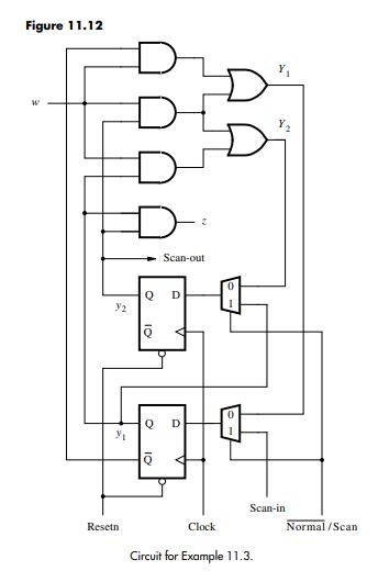
y1, and y2. Let us use the random-testing approach, choosing arbitrarily four test vectors wy1y2 = 001, 110, 100, and 111. To apply the first test vector, the pattern y1y2 = 01 is scanned into the flip-flops during two clock cycles. Then for one clock cycle, the circuit is made to operate in the normal mode with w = 0. This essentially applies the vector wy1y2 = 001 to the AND-OR circuit. The result of this test should be z = 0, Y1 = 0, and Y2 = 0. The value of z can be observed directly. The values of Y1 and Y2 are loaded into the respective flip-flops, and they are scanned out during the next two clock cycles. As these values are being scanned out, the next test pattern y1y2 = 10 can be scanned in. Thus it takes five cycles to perform one test, but the last two cycles are overlapped with the second test. The third and fourth tests are performed in the same way. The total time needed to perform all four tests is 14 clock cycles.
The preceding approach is based on testing a sequential circuit by testing its combinational part using the techniques developed in the previous sections. The scan-path facility makes it also possible to test the sequential circuit by making it go through all transitions specified in the state table. The circuit can be placed into a given state simply by scanning into the flip-flops the valuation of the state variables that denotes this state. The result of the transition can be checked by observing the primary outputs and by scanning out the valuation that presents the destination state. We leave it to the reader to develop the details of this approach.
One limitation of the scan-path technique is that it does not work well if the asynchronous preset and reset features of the flip-flops are used during normal operation. We have already suggested that it is better to use synchronous preset and reset. If the designer wishes to use the asynchronous preset and reset capability, then a testable circuit can be designed using techniques such as the level-sensitive scan design [1, 9]. The reader can consult the references for a description of this technique.
W V Y Resetn Q 10 O 10 Q Scan-out D D V Clock Y Y Scan-in Normal/Scan
Step by Step Solution
3.39 Rating (158 Votes )
There are 3 Steps involved in it
To create a table that will help in testing the finite state machine FSM by making it go through all the transitions given in the state table Figure 6... View full answer

Get step-by-step solutions from verified subject matter experts