

Question: Figure P7 illustrates a robot arm that has two links connected by two jointsa shoulder or base joint and an elbow joint. There is a
Figure P7 illustrates a robot arm that has two “links” connected by two “joints”—a shoulder or base joint and an elbow joint. There is a motor at each joint. The joint angles are θ1 and θ2. The (x, y) coordinates of the hand at the end of the arm are given by
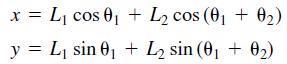
where L1 and L2 are the lengths of the links.
Polynomials are used for controlling the motion of robots. If we start the arm from rest with zero velocity and acceleration, the following polynomials are used to generate commands to be sent to the joint motor controllers
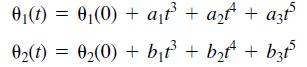
where θ1(0) and θ2(0) are the starting values at time t = 0. The angles θ1(tf) and θ2(tf) are the joint angles corresponding to the desired destination of the arm at time tf. The values of θ1(0), θ2(0), θ1(tf), and θ2(tf) can be found from trigonometry, if the starting and ending (x, y) coordinates of the hand are specified.
a. Set up a matrix equation to be solved for the coefficients a1, a2, and a3, given values for θ1(0), - θ1(tf), and tf. Obtain a similar equation for the coefficients b1, b2, and b3.
b. Use MATLAB to solve for the polynomial coefficients given the values
tf = 2 sec, θ1(0) = -19°, θ2(0) = 44°, θ1(tf) = 43°, and θ2(tf) = 151..
(These values correspond to a starting hand location of x = 6.5, y = 0 ft and a destination location of x = 0, y = 2 ft for L1 = 4 and L2 = 3 ft.)
c. Use the results of part b to plot the path of the hand.
x = L, cos 0, + L2 cos (01 + 02) y = L, sin 01 + L2 sin (01 + 02)
Step by Step Solution
3.44 Rating (154 Votes )
There are 3 Steps involved in it
It seems youre working on a problem that involves the kinematics and control of a twolink robotic arm and the task here is to solve for polynomial coefficients to control the arms movement a To set up ... View full answer

Get step-by-step solutions from verified subject matter experts