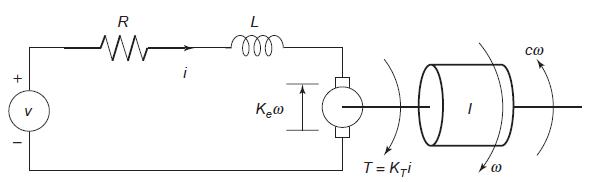
The equations for the armature-controlled dc motor shown in Figure P13 follow. The motors current is i,
Question:
The equations for the armature-controlled dc motor shown in Figure P13 follow. The motor’s current is i, and its rotational velocity is 2.
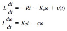
where L, R, and I are the motor’s inductance, resistance, and inertia; KT and Ke are the torque constant and back-emf constant; c is a viscous damping constant; and υ(t) is the applied voltage.
a. Find the characteristic polynomial.
b. Use the values R = 0.8 Ω, L = 0.003 H, KT = 0.05 N ∙ m/A, Ke = 0.05 V ∙ s/rad, and I = 8 × 10⁻⁵ kg ∙ m2. The damping constant c is often dif cult to determine with accuracy. For these values find the expressions for the two characteristic roots in terms of c.
c. Using the parameter values in part b, determine the roots for the following values of c (in N ∙ m ∙ s): c = 0, c = 0.01, c = 0.1, and c = 0.2. For each case, use the roots to estimate how long the motor’s speed will take to become constant; also discuss whether the speed will oscillate before it becomes constant.
Figure P13
Step by Step Answer:
Part...View the full answer