

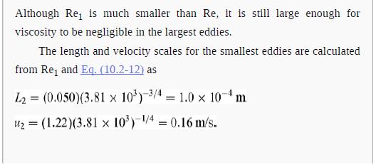
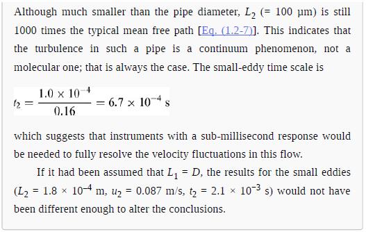
As shown in Fig. 10.5, the velocity profile in a tube at Re = 4.1 10
Question:
As shown in Fig. 10.5, the velocity profile in a tube at Re = 4.1 × 10⁴ is represented quite well by a 1⁄7-power relationship. The objective is to see what this implies about the magnitude of the mixing length.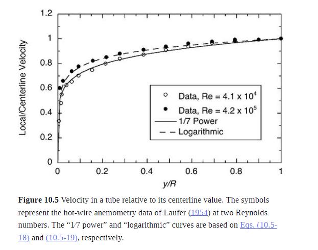
(a) For flow in a tube of radius R at the stated Re, derive the relationship between ℓ⁄R and y⁄R that is implied by the 1⁄7-power velocity profile. Note that this result will be unrealistic near the centerline, as discussed in Problem 10.8.
(b) For the region near the wall, where the 1⁄7-power profile is inapplicable because it yields an infinite shear rate at the surface, derive the relationship between ℓ⁄R and y⁄R that is implied by Eq. (10.4-10).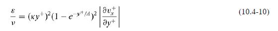
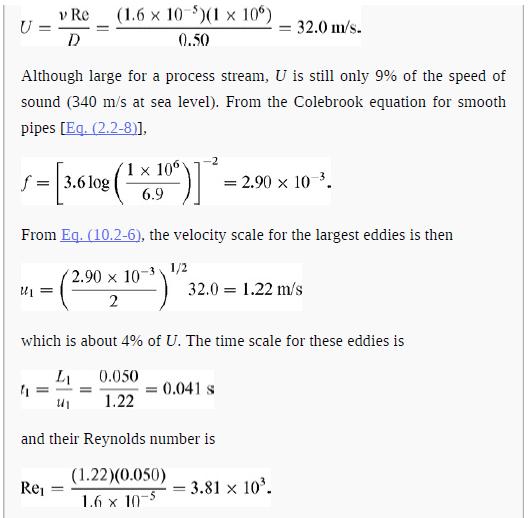
(c) Use the results from parts (a) and (b) to plot ℓ⁄R as a function of y⁄R. It is suggested that the expression from part (a) be restricted to 0.04 < y⁄R < 0.9. Your plot should show that ℓ⁄R ∼ 0.1. That is what supports the assertion in Example 10.2-1 that 0.1D is a better estimate of the largest eddy sizes than is D.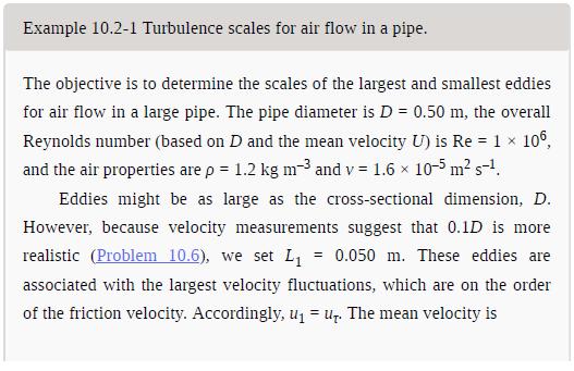
Data from Problem 10.8:
A weakness of both the power-law and logarithmic velocity profiles is that they give![]()
at y = R. Because symmetry requires that the shear stress vanish at the centerline, this implies that ε → 0 as y → R. The idea that turbulent eddies somehow disappear at the center of a tube is unrealistic and can create errors in heat and mass transfer calculations. A way around this problem was proposed by Reichardt (1951), who suggested that the eddy diffusivity outside the wall region be approximated as
where η = r⁄R, R+ is as defined in Eq. (10.2-6), and κ is an empirical constant.
(a) Show that the Reichardt eddy diffusivity leads to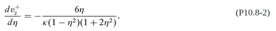
where C is a constant.
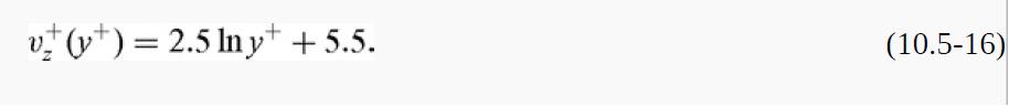
(c) Where the law of the wall applies, η → 1. By choosing κ and C for consistency with Eq. (10.5-16), show that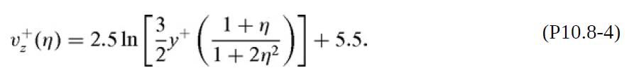
Note that the right-hand side could be rewritten in terms of η alone, if desired, by using y+ = R+(1 − η).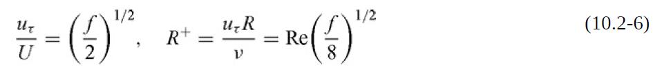
Step by Step Answer:

This question has not been answered yet.
You can Ask your question!


Introduction To Chemical Engineering Fluid Mechanics
ISBN: 9781107123779
1st Edition
Authors: William M. Deen
