

Figure P2.9 shows the layout of a microfluidic device with both series and parallel channels. The first
Question:
Figure P2.9 shows the layout of a microfluidic device with both series and parallel channels. The first segment has a length L1 = 1 mm and the relative lengths of the others are as indicated. Suppose that each channel has a square cross-section with side length 100 μm and that all flow is horizontal. The overall pressure drop for water is PA – PD = 3000 Pa. You may assume that the channels are long enough that the extra resistances associated with the bends and junctions are negligible.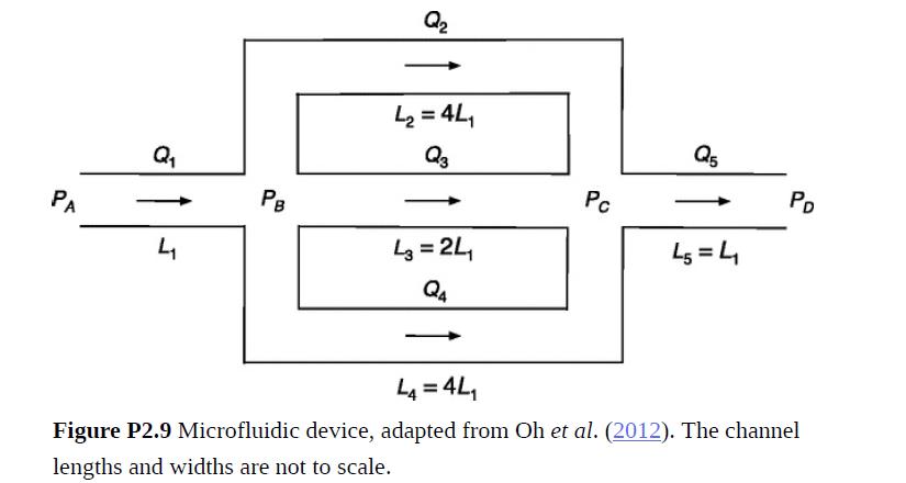
(a) Evaluate the flow-rate ratios Q2/Q1, Q3/Q1, Q4/Q1, and Q5/Q1.
(b) Calculate Q1.
Fantastic news! We've Found the answer you've been seeking!
Step by Step Answer:

Answered By
Rehab Rahim
I am well versed in communicating and teaching in areas of all business subjects. I have helped many students in different ways from answering answers to writing their academic papers.
1+ Reviews
10+ Question Solved
Related Book For 

Introduction To Chemical Engineering Fluid Mechanics
ISBN: 9781107123779
1st Edition
Authors: William M. Deen
Question Posted:
