

Draw the free-body diagram of the main shaft portion, labeled A, B, and C. Include any unbalanced
Question:
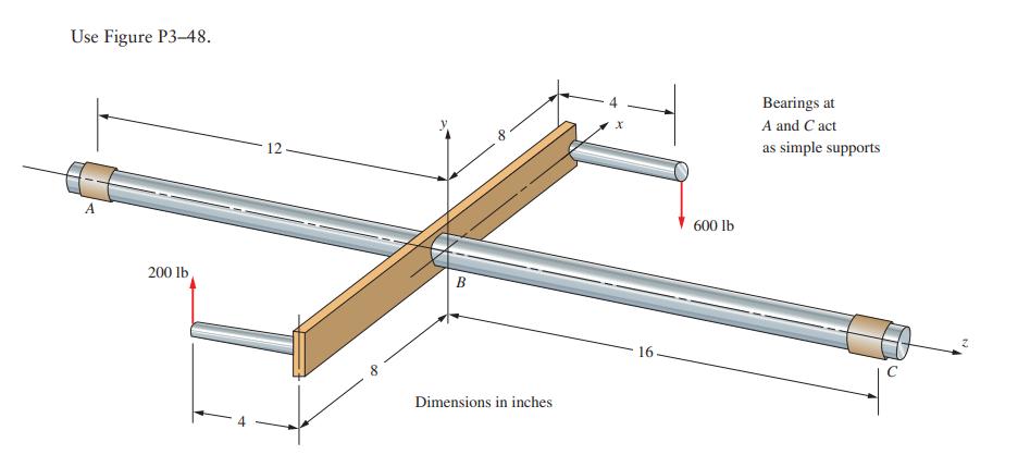
Draw the free-body diagram of the main shaft portion, labeled A, B, and C. Include any unbalanced torque on the shaft that tends to rotate it about the z-axis. In each case, the reaction to the unbalanced torque is taken at the right end of the shaft labeled C. Then draw the complete shearing force and bending moment diagrams for loading in the y–z plane. Also prepare a graph of the torque in the shaft as a function of position along the shaft from A to C.
Fantastic news! We've Found the answer you've been seeking!
Step by Step Answer:
Given the image we need to draw 1 The freebody diagram FBD of the main shaft 2 Shearing force diagram 3 Bending moment diagram 4 Torque diagram along the shaft Lets start with the freebody diagram Fre...View the full answer

Answered By
GERALD KAMAU
non-plagiarism work, timely work and A++ work
6+ Reviews
11+ Question Solved
Related Book For 
Machine Elements In Mechanical Design
ISBN: 9780134441184
6th Edition
Authors: Robert Mott, Edward Vavrek, Jyhwen Wang
Question Posted:
