

Question: Figure Q2(a) shows an active filter circuit. Vi R= 10k CH= 0.1 F 46 -1 (1) RE190KQ +9V A -9V RH=10kQ R= 10kn R=
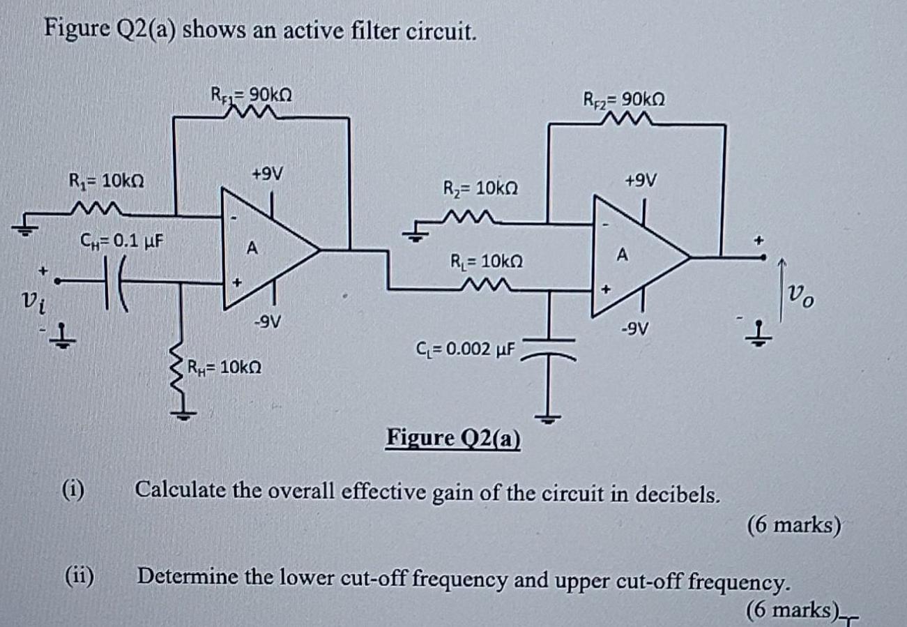
Figure Q2(a) shows an active filter circuit. Vi R= 10k CH= 0.1 F 46 -1 (1) RE190KQ +9V A -9V RH=10kQ R= 10kn R= 10kn C=0.002 F T RF2=90k +9V -9V Figure Q2(a) Calculate the overall effective gain of the circuit in decibels. Vo (6 marks) Determine the lower cut-off frequency and upper cut-off frequency. (6 marks)
Step by Step Solution
★★★★★
3.46 Rating (149 Votes )
There are 3 Steps involved in it
1 Expert Approved Answer
Step: 1 Unlock

The overall effective gain of the active filter cir... View full answer
Question Has Been Solved by an Expert!
Get step-by-step solutions from verified subject matter experts
Step: 2 Unlock
Step: 3 Unlock