

Question: The drilling machine shown in Fig. 5.29 (a) can be modeled as a two-degree-of-freedom system as indicated in Fig. 5.29(b). Since a transverse force applied
The drilling machine shown in Fig. 5.29 (a) can be modeled as a two-degree-of-freedom system as indicated in Fig. 5.29(b). Since a transverse force applied to mass \(m_{1}\) or mass \(m_{2}\) causes both the masses to deflect, the system exhibits elastic coupling. The bending stiffnesses of the column are given by (see Section 6.4 for the definition of stiffness influence coefficients)
\[k_{11}=\frac{768}{7} \frac{E I}{l^{3}}, \quad k_{12}=k_{21}=-\frac{240}{7} \frac{E I}{l^{3}}, \quad k_{22}=\frac{96}{7} \frac{E I}{l^{3}}\]
Determine the natural frequencies of the drilling machine.
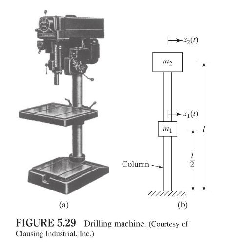
(a) Column- m2 (1)7x -x1(1) m1 (b) FIGURE 5.29 Drilling machine. (Courtesy of Clausing Industrial, Inc.)
Step by Step Solution
3.45 Rating (161 Votes )
There are 3 Steps involved in it

Get step-by-step solutions from verified subject matter experts