

Question: Consider the control system discussed in the last two long paragraphs of Box 22.2. It has GH = (1+ iz)[iz(1 iz)] 1 , with z
Consider the control system discussed in the last two long paragraphs of Box 22.2. It has G̃H̃ = −κ(1+ iz)[iz(1− iz)]−1, with z = ωτ a dimensionless frequency and τ some time constant.
(a) Show that there are no poles of D = 1+ G̃H̃ in the upper half of the complex frequency plane (z plane).
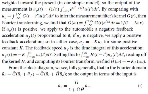
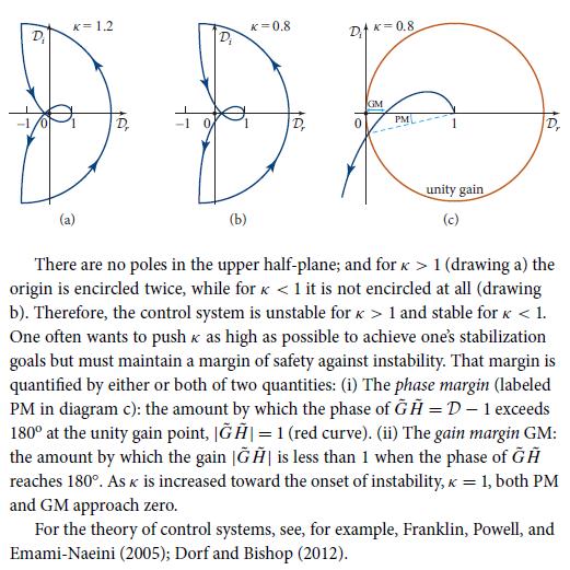
(b) Construct the Nyquist diagram for various feedback strengths κ. Show that for κ > 1 the curve encircles the origin twice (diagram a in the third figure in Box 22.2), so the control system is unstable, while for κ
(c) Show that the phase margin and gain margin, defined in diagram c in the third figure in Box 22.2, approach zero as κ increases toward the instability point, κ = 1.
(d) Compute explicitly the zeros of D = 1 + G̃H̃, and plot their trajectories in the complex frequency plane as κ increases from zero through one to ∞. Verify that two zeros enter the upper half of the frequency plane as κ increases through one, and they remain in the upper half-plane for all κ > 1, as is guaranteed by the Nyquist diagrams.
Box 22.2
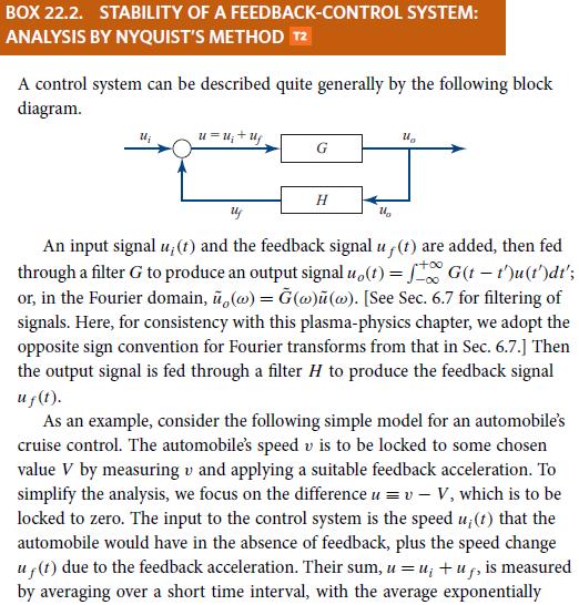
BOX 22.2. STABILITY OF A FEEDBACK-CONTROL SYSTEM: ANALYSIS BY NYQUIST'S METHOD T2 A control system can be described quite generally by the following block diagram. u=U+U G H U An input signal u; (t) and the feedback signal uf(t) are added, then fed through a filter G to produce an output signal uo(t)=G(t-t')u(t')dt'; or, in the Fourier domain, u,(w) = G(w)u(w). [See Sec. 6.7 for filtering of signals. Here, for consistency with this plasma-physics chapter, we adopt the opposite sign convention for Fourier transforms from that in Sec. 6.7.] Then the output signal is fed through a filter H to produce the feedback signal uf(t). U As an example, consider the following simple model for an automobile's cruise control. The automobile's speed v is to be locked to some chosen value V by measuring v and applying a suitable feedback acceleration. To simplify the analysis, we focus on the difference u = v - V, which is to be locked to zero. The input to the control system is the speed u; (t) that the automobile would have in the absence of feedback, plus the speed change uf(t) due to the feedback acceleration. Their sum, u = u +uf, is measured by averaging over a short time interval, with the average exponentially
Step by Step Solution
3.31 Rating (151 Votes )
There are 3 Steps involved in it

Get step-by-step solutions from verified subject matter experts