

Question: Using x r (t) = m(t) cos(2Ïf c t) and e 0 (t) = 2 cos (2Ïf c t + θ) for the assumed Costas
Figure 4.26
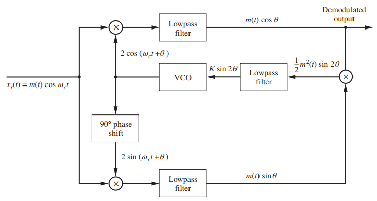
Demodulated m(t) cos 0 output Lowpass filter 2 cos (@t +0) m(1) sin 20 K sin 20 Lowpass filter VCO x,(1) = m(t) cos @d 90 phase shift 2 sin (@t +0) m(t) sin 0 Lowpass filter )
Step by Step Solution
★★★★★
3.31 Rating (148 Votes )
There are 3 Steps involved in it
1 Expert Approved Answer
Step: 1 Unlock

The Costas PLL is shown in Figure 426 The output of the top multiplier is mtco... View full answer
Question Has Been Solved by an Expert!
Get step-by-step solutions from verified subject matter experts
Step: 2 Unlock
Step: 3 Unlock