

1: Build the circuit shown in Fig. 1 in Multisim Live and use the 3-terminal op-amp model....
Question:
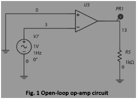
1: Build the circuit shown in Fig. 1 in Multisim Live and use the 3-terminal op-amp model. Run the simulation. What is the output of the circuit? Briefly explain why such an output is observed.
2: Change the source frequency to 100 Hz, 1 MHz and 10 MHz. Run the corresponding simulations. What are the outputs? As you increase the source frequency, what happens to the output voltage?
Open the op-amp setting, and change the V omp and V omn from the default values to 100 V and -100 V, respectively. These changes the power supply provided to the op-amp.
3: Repeat the steps of 01 and Q2. What are the outputs now at 1 Hz, 100 Hz, 1 MHz and 10 MHz? What happens to the output voltage when you increase the source frequency? Q4: Comparing the results you have obtained from Q1-Q3, how does the op-amp voltage supply affect the output (i.e., gain)?
Run an AC Sweep Analysis of the circuit shown in Fig. 1 (keep V omp and V omn at 100 V and -100 V, respectively).
Expert Answer:
1 Output Voltage of the above circuit Vrms 12V Explanation Open loop gain of the operational amplifi... View the full answer


Essentials of Contemporary Management
ISBN: ?978-0077439477
5th edition
Authors: Gareth Jones, Jennifer George
