

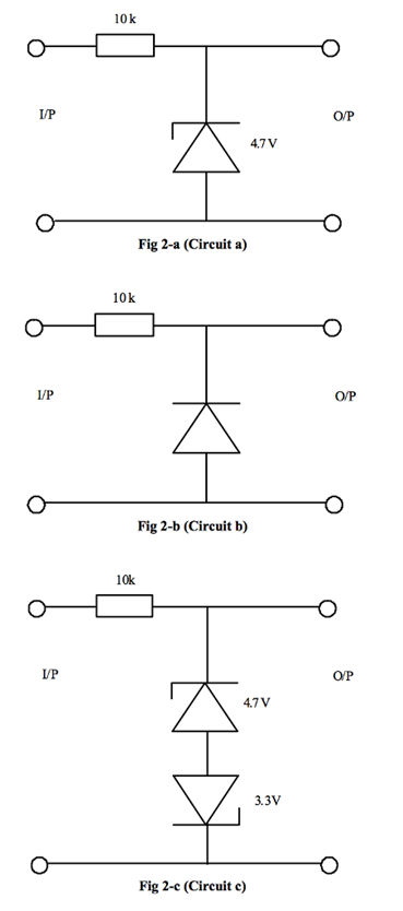
A 5 Volt peak Sine wave is applied to the diode-circuits shown in (Fig 2-a, b and
Fantastic news! We've Found the answer you've been seeking!
Question:
A 5 Volt peak Sine wave is applied to the diode-circuits shown in (Fig 2-a, b and c). Use MULTISIM to create the three circuits individually using actual diodes (google the diode values shown to choose an actual diode that can be used if the circuits were to be built practically (using actual components / boards and instruments) and print a fully labelled diagram of the circuits with the function generator / oscilloscope displays showing both the input signal (as channel 1) and the output signal (as channel 2) for each circuit. All voltage levels MUST be shown.
Expert Answer:

Related Book For 

Fundamentals of Electric Circuits
ISBN: 9780073301150
3rd edition
Authors: Matthew Sadiku, Charles Alexander
Posted Date:
