

Question: 1 . 3 1 0 2 0 1 . 3 1 0 2 0 electrons flow through a cross section of a 2 . 1
electrons flow through a cross section of ammmmdiameteriron wire ins The truss in the following figure has a times lower chord of Select Structural SPF South SprucePineFir and a times top chord of No Hemfir. The loads shown are the results of Dmathrmpsf and S psf acting vertically over the span. There is no reduction of area for fasteners. CM CtCi Joints are assumed to be pinconnected. Trusses are spaced ft on center. The top of the truss is fully supported along its length by roof sheathing. Check the combined compression and bending in the top chord using LRFD
Please note that this is the same structure of your Homework # Problem Follow this structural analysis guideline to estimate the bending moment in the top chord and additional distributed force at the top chord cause by
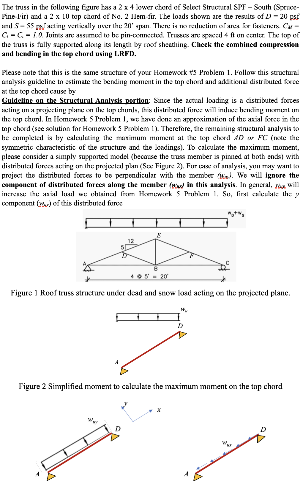
Guideline on the Structural Analysis portion: Since the actual loading is a distributed forces acting on a projecting plane on the top chords, this distributed force will induce bending moment on the top chord. In Homework Problem we have done an approximation of the axial force in the top chord see solution for Homework Problem Therefore, the remaining structural analysis to be completed is by calculating the maximum moment at the top chord A D or F C note the symmetric characteristic of the structure and the loadings To calculate the maximum moment, please consider a simply supported model because the truss member is pinned at both ends with distributed forces acting on the projected plan See Figure For ease of analysis, you may want to project the distributed forces to be perpendicular with the member underlineww We will ignore the component of distributed forces along the member underlinewu x in this analysis. In general, underlinewuj underlineg will increase the axial load we obtained from Homework Problem So first calculate the y component underlinewunderlineu v of this distributed force
Figure Roof truss structure under dead and snow load acting on the projected plane.
Figure Simplified moment to calculate the maximum moment on the top chord
Step by Step Solution
There are 3 Steps involved in it
1 Expert Approved Answer
Step: 1 Unlock

Question Has Been Solved by an Expert!
Get step-by-step solutions from verified subject matter experts
Step: 2 Unlock
Step: 3 Unlock