

Question: 1 9 - 1 0 . Using Figure P - 1 9 - 9 , lay out the sewer lines ( placement , direction of
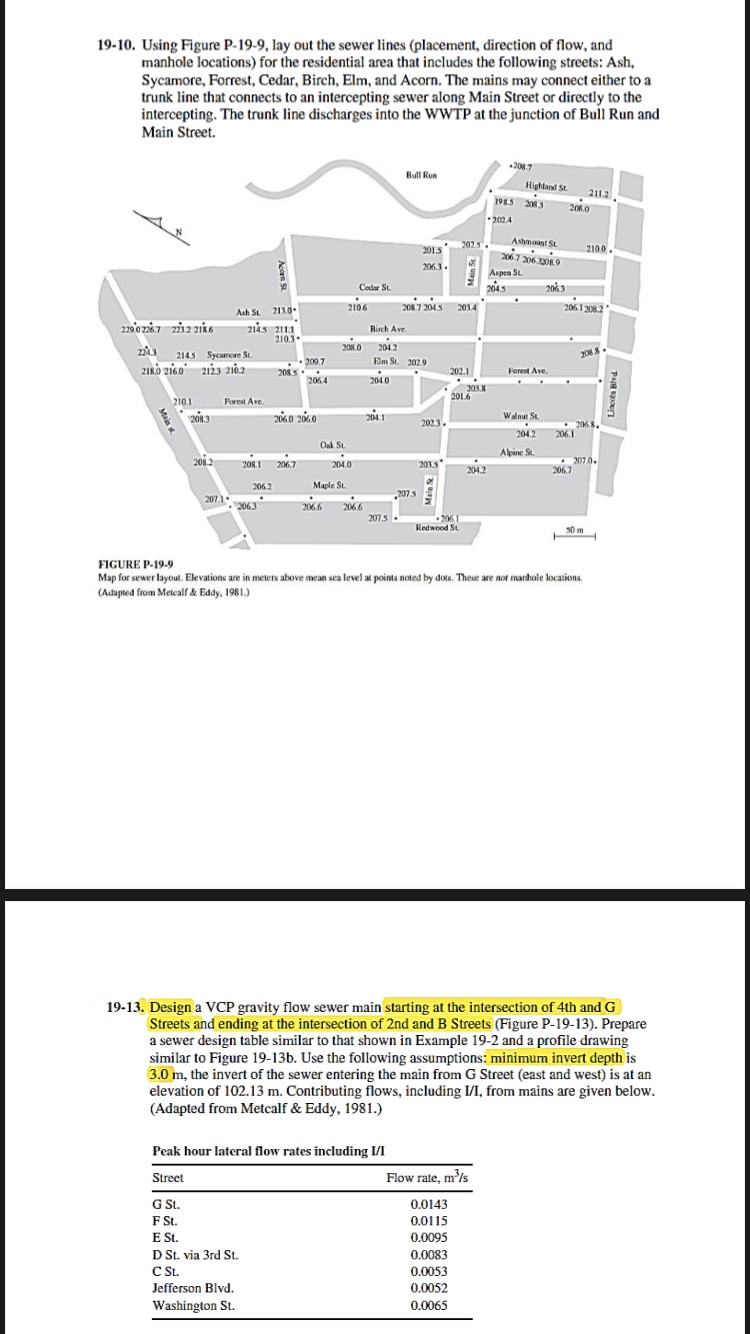
Using Figure P lay out the sewer lines placement direction of flow, and
manhole locations for the residential area that includes the following streets: Ash,
Sycamore, Forrest, Cedar, Birch, Elm, and Acorn. The mains may connect either to a
trunk line that connects to an intercepting sewer along Main Street or directly to the
intercepting. The trunk line discharges into the WWTP at the junction of Bull Run and
Main Street.
FIGURE P
Map for sewer layout. Elevations are in meters above mean sea level at points noted by does. These are not manhole locations.
Adapicd from Mcicalf & Eddy, Using Figure P lay out the sewer lines placement direction of flow, and
manhole locations for the residential area that includes the following streets: Ash,
Sycamore, Forrest, Cedar, Birch, Elm, and Acorn. The mains may connect either to a
trunk line that connects to an intercepting sewer along Main Street or directly to the
intercepting. The trunk line discharges into the WWTP at the junction of Bull Run and
Main Street.
Design a VCP gravity flow sewer main starting at the intersection of th and G
Streets and ending at the intersection of nd and B Streets Figure P Prepare
a sewer design table similar to that shown in Example and a profile drawing
similar to Figure b Use the following assumptions: minimum invert depth is
the invert of the sewer entering the main from G Street east and west is at an
elevation of Contributing flows, including II from mains are given below.
Adapted from Metcalf & Eddy, Figure P Map for Problem Elevations are in meters at points noted by dots. These are also manhole locations. Adapted from Metcalf & Eddy, Design a VCP gravity flow sewer main starting at the intersection of th and G
Streets and ending at the intersection of nd and B Streets Figure P Prepare
a sewer design table similar to that shown in Example and a profile drawing
similar to Figure b Use the following assumptions: minimum invert depth is
the invert of the sewer entering the main from G Street east and west is at an
elevation of Contributing flows, including from mains are given below.
Adapted from Metcalf & Eddy,
Peak hour lateral flow rates including II
Peak hour lateral flow rates including
Step by Step Solution
There are 3 Steps involved in it
1 Expert Approved Answer
Step: 1 Unlock

Question Has Been Solved by an Expert!
Get step-by-step solutions from verified subject matter experts
Step: 2 Unlock
Step: 3 Unlock