

Question: 1. Company Change Order - Modify/Redline P&ID (5 Marks) The Sump System below will be modified to replace the level Transmitter with a Level Switch
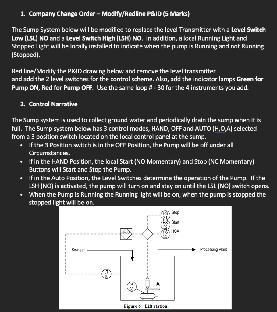
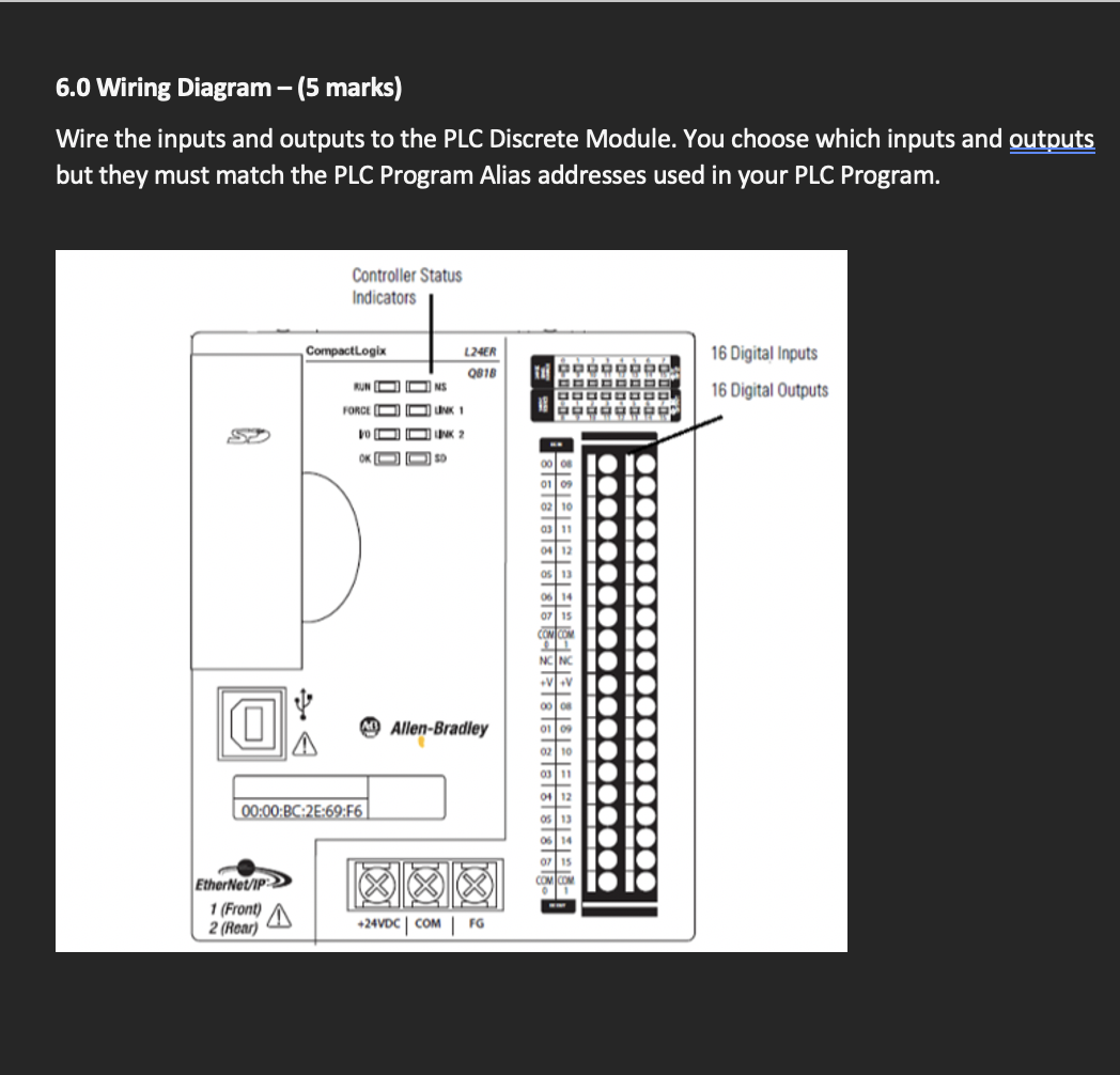
1. Company Change Order - Modify/Redline P&ID (5 Marks) The Sump System below will be modified to replace the level Transmitter with a Level Switch Low (LSL) NO and a Level Switch High (LSH) NO. In addition, a local Running Light and Stopped Light will be locally installed to indicate when the pump is Running and not Running (Stopped). Red line/Modify the P&ID drawing below and remove the level transmitter and add the 2 level switches for the control scheme. Also, add the indicator lamps Green for Pump ON, Red for Pump OFF. Use the same loop # - 30 for the 4 instruments you add. 2. Control Narrative The Sump system is used to collect ground water and periodically drain the sump when it is full. The Sump system below has 3 control modes, HAND, OFF and AUTO (H.0,A) selected from a 3 position switch located on the local control panel at the sump. If the 3 Position switch is in the OFF Position, the Pump will be off under all Circumstances. If in the HAND Position, the local Start (NO Momentary) and Stop (NC Momentary) Buttons will start and Stop the Pump. If in the Auto Position, the Level Switches determine the operation of the Pump. If the LSH (NO) is activated, the pump will turn on and stay on until the LSL (NO) switch opens. When the Pump is Running the Running light will be on, when the pump is stopped the stopped light will be on. . Stop 2823 HS Start -30 HS HOA Sewage Processing Plant Figure 6 - Lift station. 3.0 Logic Diagram (5 Marks) Design the control system using Boolean Gates (use Multimedia Logic if desired) 4.0 Boolean Expression (2 Marks) From the design of the Logic Diagram, develop the Boolean expression for the pump. 5.0 Ladder Diagram (8 marks) Program the control system in Ladder Diagram 6.0 Wiring Diagram - (5 marks) Wire the inputs and outputs to the PLC Discrete Module. You choose which inputs and outputs but they must match the PLC Program Alias addresses used in your PLC Program. Controller Status Indicators CompactLogix L24ER 0818 16 Digital Inputs 10 RUNO DNS 16 Digital Outputs FORCE UN 1 10 NK 2 OKOSO slalalalalalala.get:lalalalalalalala Elusllllll My Allen-Bradley A 00:00:BC:28:69:F6 EtherNet/IP 1 (Front) FG 2 (Rear) +24VDC COM
Step by Step Solution
There are 3 Steps involved in it

Get step-by-step solutions from verified subject matter experts