

Question: 1 . Compute the total force ( kip ) transferred from the windward wall to the second floor diaphragm. 2 . Compute the total force
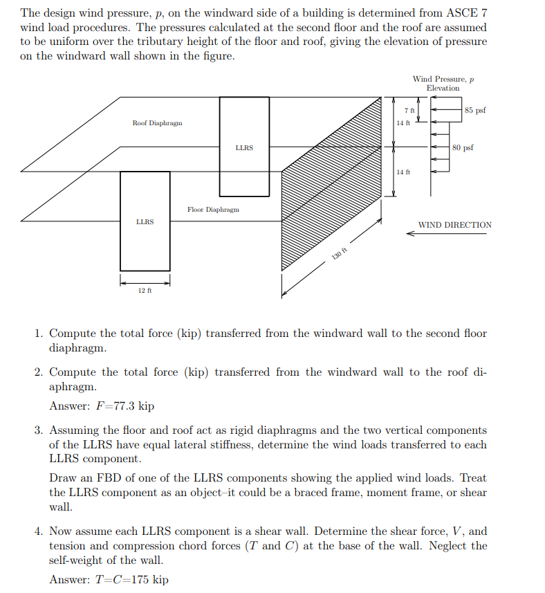
Compute the total force kip transferred from the windward wall to the second floor diaphragm. Compute the total force kip transferred from the windward wall to the roof diaphragm. Answer: F kip Assuming the floor and roof act as rigid diaphragms and the two vertical components of the LLRS have equal lateral stiffness, determine the wind loads transferred to each LLRS component. Draw an FBD of one of the LLRS components showing the applied wind loads. Treat the LLRS component as an objectit could be a braced frame, moment frame, or shear wall. Now assume each LLRS component is a shear wall. Determine the shear force, V and tension and compression chord forces T and C at the base of the wall. Neglect the selfweight of the wall. Answer: TC kip The design wind pressure, p on the windward side of a building is determined from ASCE wind load procedures. The pressures calculated at the second floor and the roof are assumed to be uniform over the tributary height of the floor and roof, giving the elevation of pressure on the windward wall shown in the figure.
Compute the total force kip transferred from the windward wall to the second floor diaphragm.
Compute the total force kip transferred from the windward wall to the roof diaphragm.
Answer: F kip
Assuming the floor and roof act as rigid diaphragms and the two vertical components of the LLRS have equal lateral stiffness, determine the wind loads transferred to each LLRS component.
Draw an FBD of one of the LLRS components showing the applied wind loads. Treat the LLRS component as an objectit could be a braced frame, moment frame, or shear wall.
Now assume each LLRS component is a shear wall. Determine the shear force, V and tension and compression chord forces T and C at the base of the wall. Neglect the selfweight of the wall.
Answer: TC kip
Step by Step Solution
There are 3 Steps involved in it
1 Expert Approved Answer
Step: 1 Unlock

Question Has Been Solved by an Expert!
Get step-by-step solutions from verified subject matter experts
Step: 2 Unlock
Step: 3 Unlock