

Question: 1) Consider the following 4-bit DAC shown below, which has a reference voltage of 5 Volts. Apply the digital data to inputs A to D
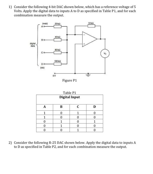
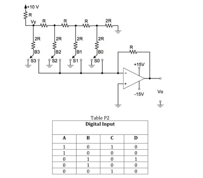
1) Consider the following 4-bit DAC shown below, which has a reference voltage of 5 Volts. Apply the digital data to inputs A to D as specified in Table P1, and for each combination measure the output. 2) Consider the following R-25 DAC shown below. Apply the digital data to inputs A to D as specified in Table P2, and for each combination measure the output. Table P2 \begin{tabular}{|c|c|c|c|} \hline \multicolumn{4}{|c|}{ Digital Input } \\ \hline A & B & C & D \\ \hline 1 & 0 & 1 & 0 \\ \hline 1 & 0 & 0 & 0 \\ \hline 0 & 1 & 0 & 1 \\ \hline 0 & 1 & 0 & 0 \\ \hline 0 & 0 & 1 & 0 \\ \hline \end{tabular}
Step by Step Solution
There are 3 Steps involved in it
1 Expert Approved Answer
Step: 1 Unlock

Question Has Been Solved by an Expert!
Get step-by-step solutions from verified subject matter experts
Step: 2 Unlock
Step: 3 Unlock