

Question: 1. Consider the level control system shown in Fig T3.1, implemented with a computer whose inputs and outputs are calibrated in terms of full range
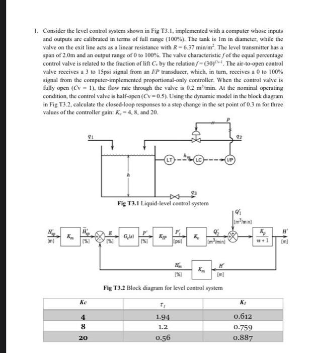
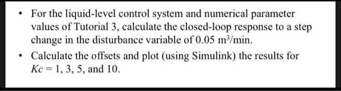
1. Consider the level control system shown in Fig T3.1, implemented with a computer whose inputs and outputs are calibrated in terms of full range (100%). The tank is 1m in diameter, while the valve on the exit line acts as a linear resistance with R=6.37min/m2. The level transmitter has a span of 2.0m and an output range of 0 to 100%. The valve characteristic f of the equal percentage control valve is related to the fraction of lift Cv by the relation f=(30)c1. The air-to-open control valve receives a 3 to 15psi signal from an IP transducer, which, in turn, receives a 0 to 100% signal from the computer-implemented proportional-only controller. When the control valve is fully open (CCV=1), the flow rate through the valve is 0.2m3/min. At the nominal operating condition, the control valve is half-open (Cv=0.5). Using the dynamic model in the block diagram in Fig T3.2, calculate the closed-loop responses to a step change in the set point of 0.3m for three values of the controller gain: Kc=4,8, and 20 . Fig T3.2 Block diagram for level control system - For the liquid-level control system and numerical parameter values of Tutorial 3 , calculate the closed-loop response to a step change in the disturbance variable of 0.05m3/min. - Calculate the offsets and plot (using Simulink) the results for Kc=1,3,5, and 10
Step by Step Solution
There are 3 Steps involved in it

Get step-by-step solutions from verified subject matter experts