

Question: 1. Create a ladder logic diagram that utilizes the LIFO and FIFO functions in SLC500 series Allen Bradley PLCs In the first part of the
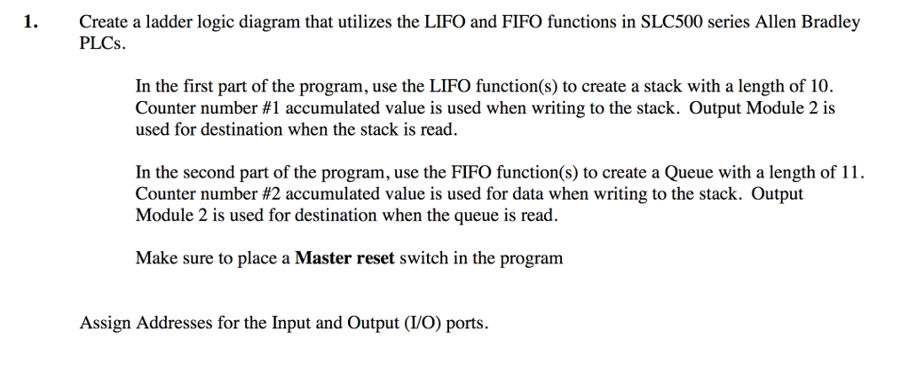
1. Create a ladder logic diagram that utilizes the LIFO and FIFO functions in SLC500 series Allen Bradley PLCs In the first part of the program, use the LIFO function(s) to create a stack with a length of 10. Counter number #1 accumulated value is used when writing to the stack. Output Module 2 is used for destination when the stack is read In the second part of the program, use the FIFO function(s) to create a Queue with a length of 1 Counter number #2 accumulated value is used for data when writing to the stack. Output Module 2 is used for destination when the queue is read. Make sure to place a Master reset switch in the program Assign Addresses for the Input and Output (VO) ports. 1. Create a ladder logic diagram that utilizes the LIFO and FIFO functions in SLC500 series Allen Bradley PLCs In the first part of the program, use the LIFO function(s) to create a stack with a length of 10. Counter number #1 accumulated value is used when writing to the stack. Output Module 2 is used for destination when the stack is read In the second part of the program, use the FIFO function(s) to create a Queue with a length of 1 Counter number #2 accumulated value is used for data when writing to the stack. Output Module 2 is used for destination when the queue is read. Make sure to place a Master reset switch in the program Assign Addresses for the Input and Output (VO) ports
Step by Step Solution
There are 3 Steps involved in it

Get step-by-step solutions from verified subject matter experts