

Question: 1. Derive the transfer function of the system shown in Figure below. Not: Answer must include all the ncesaary equations and steps V +
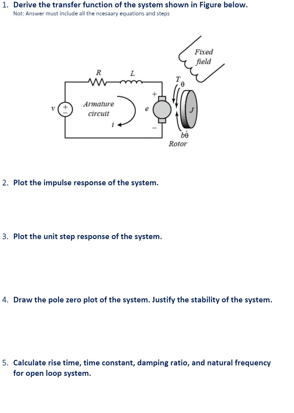
1. Derive the transfer function of the system shown in Figure below. Not: Answer must include all the ncesaary equations and steps V + R M Armature circuit i L + 2. Plot the impulse response of the system. 3. Plot the unit step response of the system. be Rotor Fixed field 4. Draw the pole zero plot of the system. Justify the stability of the system. 5. Calculate rise time, time constant, damping ratio, and natural frequency for open loop system.
Step by Step Solution
There are 3 Steps involved in it
1 Expert Approved Answer
Step: 1 Unlock

Question Has Been Solved by an Expert!
Get step-by-step solutions from verified subject matter experts
Step: 2 Unlock
Step: 3 Unlock