

Question: 1. Design by direct implementation the logic diagrams (by hand) or the following logic equations using any real 1-input, 2-input or 3-input logic gates, trying
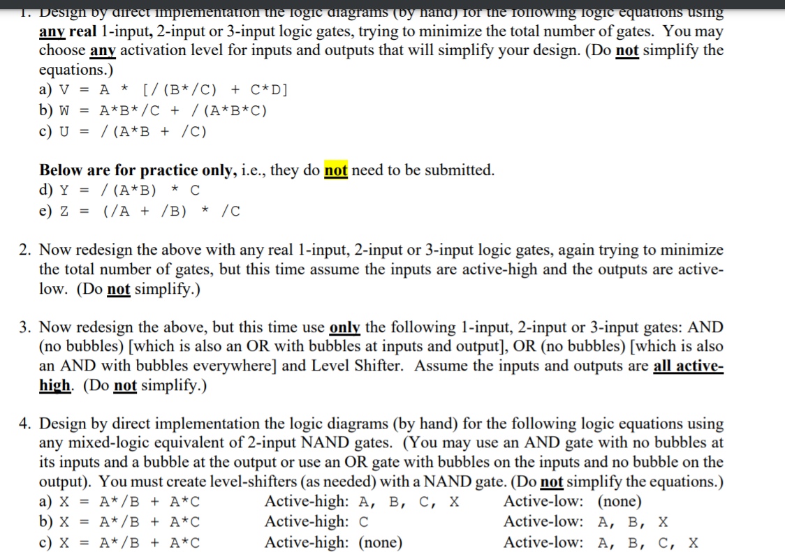
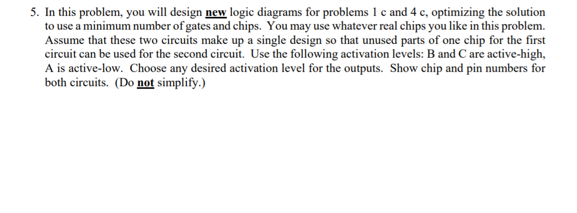
1. Design by direct implementation the logic diagrams (by hand) or the following logic equations using any real 1-input, 2-input or 3-input logic gates, trying to minimize the total number of gates. You may choose any activation level for inputs and outputs that will simplify your design. (Do not simplify the equations.) a) V = A * [/ (B*/C) + C*D] b) W = A*B*/C + / (A*B*C) c) U = / (A*B + /C) Below are for practice only, i.e., they do not need to be submitted. d) Y = / (A*B) e) Z = (A + B) * / * 2. Now redesign the above with any real 1-input, 2-input or 3-input logic gates, again trying to minimize the total number of gates, but this time assume the inputs are active-high and the outputs are active- low. (Do not simplify.) 3. Now redesign the above, but this time use only the following 1-input, 2-input or 3-input gates: AND (no bubbles) (which is also an OR with bubbles at inputs and output], OR (no bubbles) (which is also an AND with bubbles everywhere] and Level Shifter. Assume the inputs and outputs are all active- high. (Do not simplify.) 4. Design by direct implementation the logic diagrams (by hand) for the following logic equations using any mixed-logic equivalent of 2-input NAND gates. (You may use an AND gate with no bubbles at its inputs and a bubble at the output or use an OR gate with bubbles on the inputs and no bubble on the output). You must create level-shifters (as needed) with a NAND gate. (Do not simplify the equations.) a) X = A*/B + A*C Active-high: A, B, C, X Active-low: (none) b) X = A*/B + A*C Active-high: C Active-low: A, B, X c) X = A*/B + A*C Active-high: (none) Active-low: A, B, C, X 5. In this problem, you will design new logic diagrams for problems 1 c and 4 c, optimizing the solution to use a minimum number of gates and chips. You may use whatever real chips you like in this problem. Assume that these two circuits make up a single design so that unused parts of one chip for the first circuit can be used for the second circuit. Use the following activation levels: B and C are active-high, A is active-low. Choose any desired activation level for the outputs. Show chip and pin numbers for both circuits. (Do not simplify.)
Step by Step Solution
There are 3 Steps involved in it

Get step-by-step solutions from verified subject matter experts