

Question: 1 . Develop a flow chart of the process for determining the bar cutoff locations in flexural members. 2 . A rectangular beam with cross
Develop a flow chart of the process for determining the bar cutoff locations in flexural members. A rectangular beam with cross section b in h in and d in supports a total factored load of kipft including its own dead load. The beam is simply supported with a ft span. It is reinforced with five No Grade bars, two of which are cutoff between midspan and the support and three of which extend in past the centers of the supports. fc psi. normal weight The beam has Grade No stirrups satisfying ACI Code Sections and a Plot to scale the factored moment diagram. M wx wx where x is the distance from the support and is the span. b Plot the moment strength diagram and locate the cutoff point for the two cutoff bars, such that the moment strength diagram stays above the factored moment. The beam shown in Fig. is built of psi normalweight concrete and Grade steel uncoated bars. The effective depth d in The beam supports a total factored uniform load of kipsft including its own dead load. The frame is not part of the lateral loadresisting system for the building. Select cutoff points for span BC based on the following requirements: a Cut off two No positive moment bars when no longer needed at each end. Extend the remaining bars into the columns. b Extend all negativemoment bars past the negativemoment point of inflection before cutting them off Develop a flow chart of the process for determining the bar cutoff locations in flexural members.
A rectangular beam with cross section bmathrmin hmathrmin and dmathrmin supports a total factored load of mathrmkipmathrmft including its own dead load. The beam is simply supported with a ft span. It is reinforced with five No Grade bars, two of which are cutoff between midspan and the support and three of which extend mathrmin past the centers of the supports. fcprime psi. normal weight The beam has Grade No stirrups satisfying ACI Code Sections and
a Plot to scale the factored moment diagram. Mw ell x w x where x is the distance from the support and ell is the span.
b Plot the moment strength diagram and locate the cutoff point for the two cutoff bars, such that the moment strength diagram stays above the factored moment.
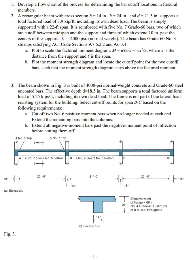
The beam shown in Fig. is built of psi normalweight concrete and Grade steel uncoated bars. The effective depth mathrmdmathrmin The beam supports a total factored uniform load of mathrmkipsmathrmft including its own dead load. The frame is not part of the lateral loadresisting system for the building. Select cutoff points for span BC based on the following requirements:
a Cut off two No positive moment bars when no longer needed at each end. Extend the remaining bars into the columns.
b Extend all negativemoment bars past the negativemoment point of inflection before cutting them off.
a Elevation.
b Section
Fig.
Step by Step Solution
There are 3 Steps involved in it
1 Expert Approved Answer
Step: 1 Unlock

Question Has Been Solved by an Expert!
Get step-by-step solutions from verified subject matter experts
Step: 2 Unlock
Step: 3 Unlock