

Question: 1. Draw the circuit for a function that is ~(PandQorR) do not use any or gates (tip: use demorgans law) 2. Draw the circuit for
1. Draw the circuit for a function that is ~(PandQorR) do not use any or gates (tip: use demorgans law)
2. Draw the circuit for ~~~P -> Q (simplify first)
3. Draw the circuit for PorQ using only NAND gates.
Been at this for hours I dont get it can anyone help me please??
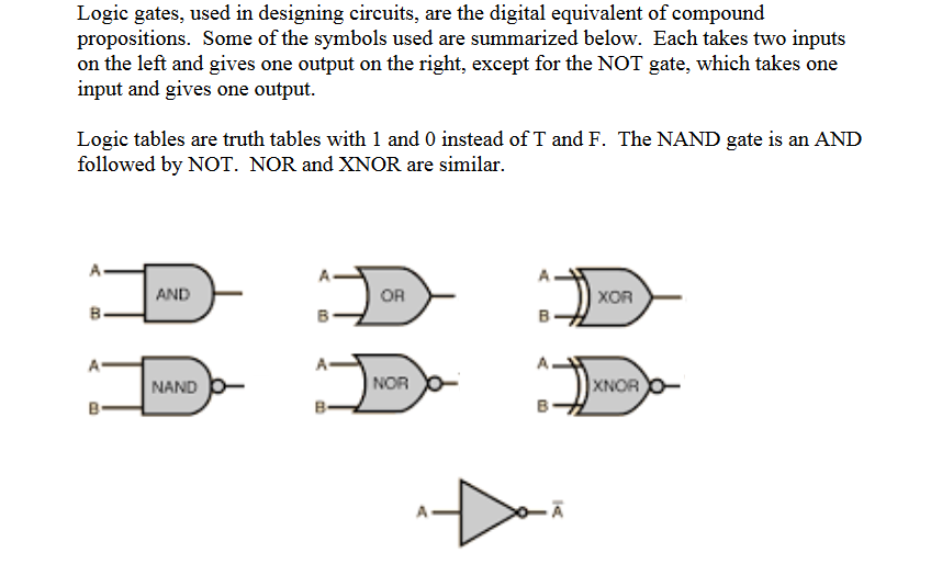
Logic gates, used in designing circuits, are the digital equivalent of compound propositions. Some of the symbols used are summarized below. Each takes two inputs on the left and gives one output on the right, except for the NOT gate, which takes one input and gives one output. Logic tables are truth tables with 1 and 0 instead of T and F. The NAND gate is an AND followed by NOT. NOR and XNOR are similar
Step by Step Solution
There are 3 Steps involved in it

Get step-by-step solutions from verified subject matter experts