

Question: 1) For the below circuits (RL and Op-Amp); a) Find the transfer function H(s) and frequency response H(jw) of each circuit. b) Determine the
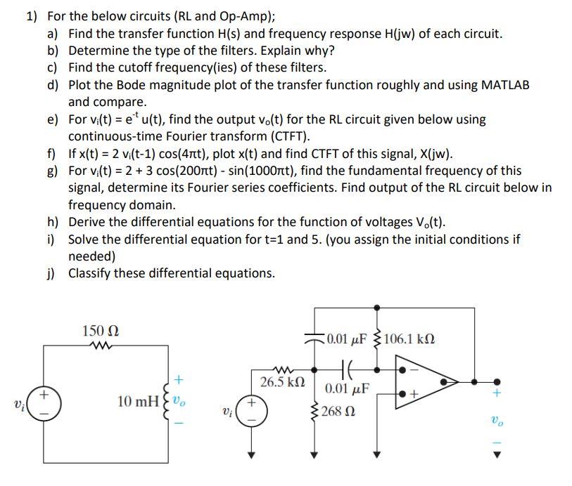
1) For the below circuits (RL and Op-Amp); a) Find the transfer function H(s) and frequency response H(jw) of each circuit. b) Determine the type of the filters. Explain why? c) Find the cutoff frequency(ies) of these filters. d) Plot the Bode magnitude plot of the transfer function roughly and using MATLAB and compare. Vil e) For vi(t) = eu(t), find the output vo(t) for the RL circuit given below using continuous-time Fourier transform (CTFT). f) If x(t) = 2 vi(t-1) cos(4nt), plot x(t) and find CTFT of this signal, X(jw). g) For vi(t) = 2 + 3 cos(200nt) - sin(1000nt), find the fundamental frequency of this signal, determine its Fourier series coefficients. Find output of the RL circuit below in frequency domain. h) Derive the differential equations for the function of voltages Vo(t). i) Solve the differential equation for t=1 and 5. (you assign the initial conditions if needed) j) Classify these differential equations. + 150 www + 10 mHo Vi 26.5 0.01 F 5106.1 HE 0.01 F 268 Vo
Step by Step Solution
3.44 Rating (154 Votes )
There are 3 Steps involved in it
An operational amplifier is an integrated circuit that can amplify weak electric signals An operatio... View full answer

Get step-by-step solutions from verified subject matter experts