

1. In Step 1 enter all the following starting criteria: Concrete unit weight = 150 pcf...
Fantastic news! We've Found the answer you've been seeking!
Question:
Transcribed Image Text:
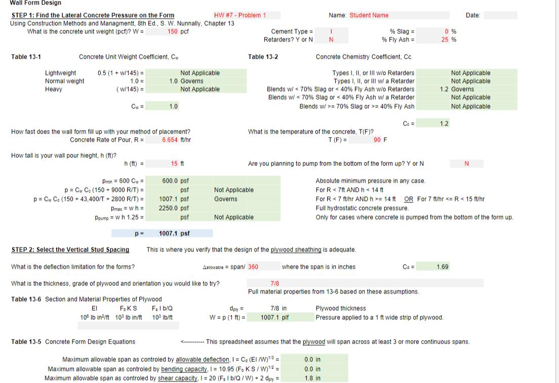
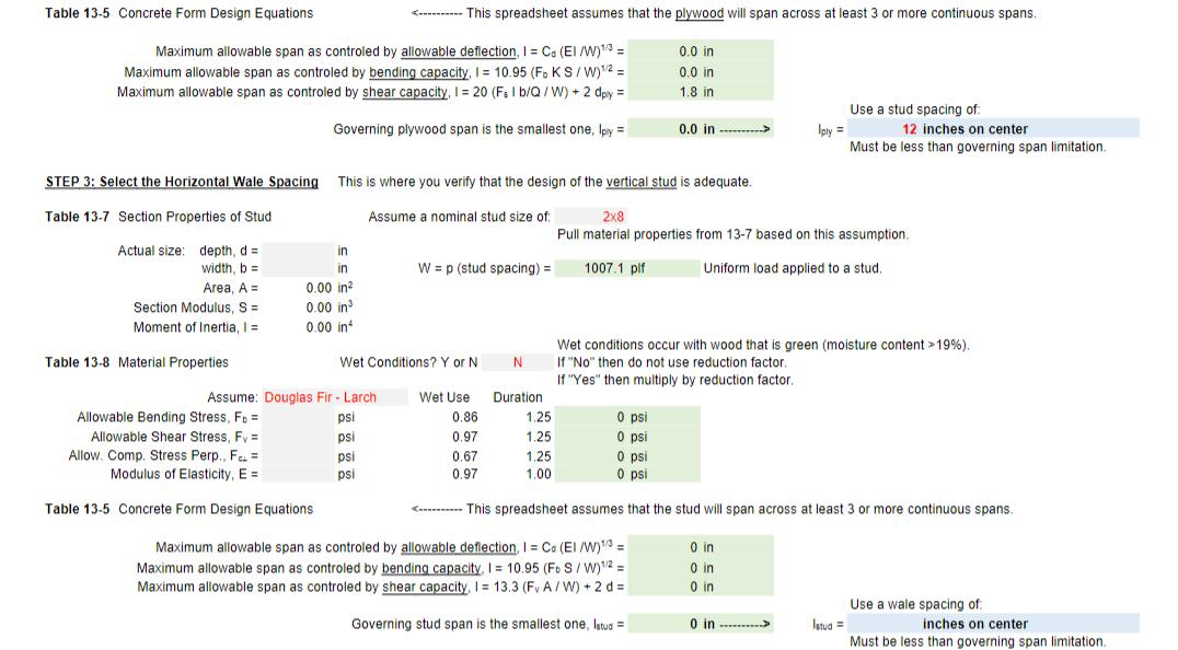
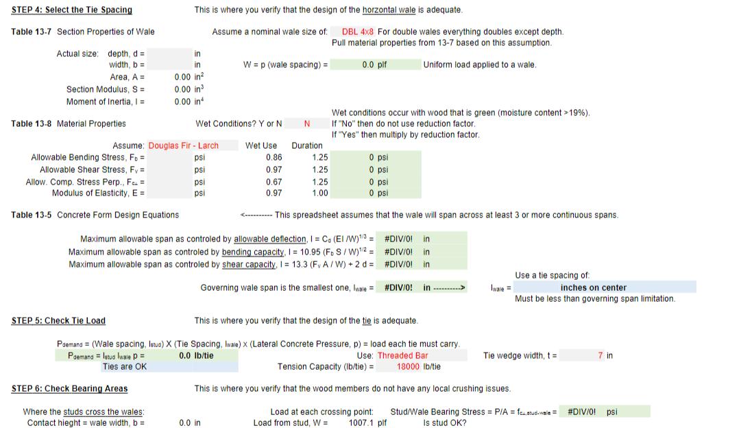
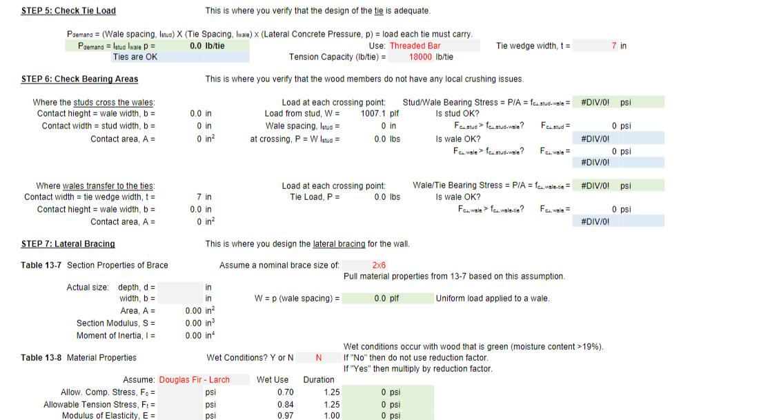
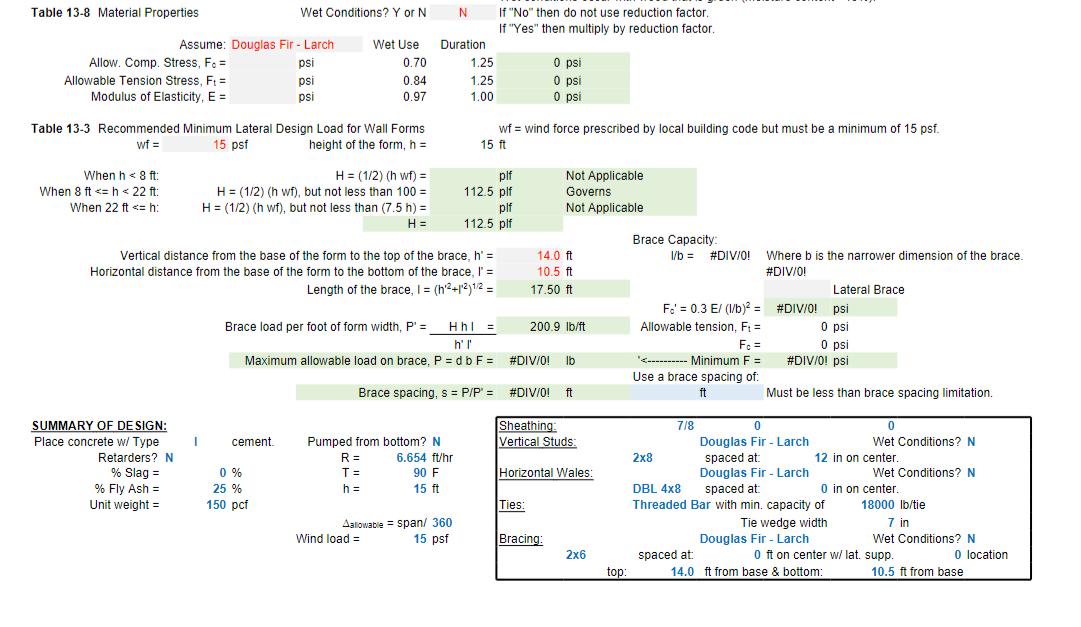
1. In Step 1 enter all the following starting criteria: Concrete unit weight = 150 pcf 1) 2) 3) 4) 5) 6) 7) Cement Type I No retarder but with 25% fly ash (no slag). Concrete rate of pour, R = 6.654 ft/hr Concrete temperature = 90 F Wall height, h = 15 ft Do not pump from the bottom of the wall. 1.1. Confirm that you got a concrete lateral wall pressure, p = 1007.1 psf. This step is just to confirm you got the basic input in correctly. It also matches the results you should have gotten on HW #6 for both parts 5.6 and 6.2. Part 8 will have you print this. 2. In Step 2 you will be optimizing the design of the Plyform which sets the vertical spacing of the studs. (11 points total) You will need to enter the following additional criteria: 8) 9) Allowable deflection, Aallowable = span/360 Use 7/8" thick Plyform sheathing. You will need to decide between three different classes of Plyform and two different grain directions giving you six options to choose from in the 7/8" thickness. 2.1. Choose the exact description of the nominal plywood thickness and grain direction into the space provided for it. See 2.2 below. Choose the Plyform from Table 13-6 that is the least expensive that allows for a vertical stud spacing of 12 inches on center. Remember in order of lowest to highest cost the options are Plyform Class I, then Class II, then Structural I. (4 points total, 2 points for the correct class and 2 points for correct reference to the direction of the grain) 2.2. To reflect the properties of your decision, enter the three section and material properties given in Table 13-6 in the spreadsheet (EI, FKS, and F.Ib/Q). The three properties are required for deflection, bending and shear calculations respectively. There is a calculation for the allowable span as governed by the Plyform's capacity for resisting deflection, bending, and shear respectively. The minimum allowable Plyform span is the governing dimension in cell 147. That dimension should not be less than 12 in and should not greatly exceed 12 inches. (3 points, 1 each) 2.3. Verify that the stud spacing in cell L47 is less than or equal to the value in 147. It should now be able to read 12 inches on center to reflect that the studs can be spaced at 12 in on center. (4 points) 3. In Step 3 you will design the studs. This also sets the spacing of the wales. You have been given the stud size below: (10 points total) You will need to enter the following additional criteria: 10) Use 2x8 Douglas Fir-Larch studs (not wet conditions) with 3 or more spans. 3.1. Enter the true stud dimensions for the depth, d and width, b from Table 13-7 that corresponds to the stud size above. (2 points) 3.2. You will also need to enter the material properties for the wood from Table 13-8. You will enter F, (allowable bending stress), F, (allowable shear stress), F allowable compression stress when the compression is applied perpendicular to the direction of the wood grains) and E (modulus of elasticity). The F is the same one as is in the third column of Table 13-7. Also, don't enter the value of E in scientific notation (ie. enter it as "1700000" instead of "1.7x106"). (4 points, 1 each) 3.3. There is a calculation for the allowable stud span as governed by the stud's capacity for resisting deflection, bending, and shear respectively. The minimum allowable stud span is the governing dimension in cell 174. Round that number down to the nearest whole number divisible by two and enter that number as the wale spacing in cell L74. (4 points) 4. In Step 4 you will design the wale. This also sets the spacing of the ties. You have been given the wale size below: (10 points total) You will need to enter the following additional criteria: 11) Use double 4x8 Douglas Fir-Larch wales (not wet conditions) with 3 or more spans. 4.1. Enter the true wale dimensions for the depth, d and width, b from Table 13-7. (2 points) 4.2. You will also need to enter the material properties for the wood from Table 13-8 or copy them down from Step 3. (4 points, 1 each) 4.3. There is a calculation for the allowable wale span as governed by the wale's capacity for resisting deflection, bending, and shear respectively. The minimum allowable wale span is the governing dimension in cell 1101. Round that number down to the nearest whole number divisible by two and enter that number as the tie spacing in cell L101. (4 points) 5. In Step 5 we must design a tie for the tension load being transferred to each tie. You will need to enter the following additional criteria: 12) Use threaded ties with a capacity to hold 18000 lb tension and a tie wedge width of 7 inches. 5.1. The tie load is the Pdemand. If this is less than the capacity of the tie you entered, then the ties are sufficient. Cell C108 should say "Ties are OK". If not, then we need a stronger tie or more ties (closer spacing). Is the tie OK? If not, then we need to reduce either the value in Step 3 or the value in Step 4. The spacing reduction should be coordinated with Steps 6.1 and 6.2 below. (5 points) 6. In Step 6 we must check that the bearing areas are not going to cause the wood fibers to crush between the studs and wales or between the wales and ties. This requires a calculation of the force at each crossing point. In the spreadsheet the linear (line) load on the stud multiplied by the wale spacing will give us the load transferred at the contact between the studs and wales. The contact area is the contact width of the stud, b x the contact width of the wale, b. The stress demand is therefore that load divided by the calculated contact area. This stress demand is given in the green shaded cell, M112. The two numbers below it are just the factored F from H65 and H92 for the stud and the wale respectively. These must be factored to account for wet use and load duration. (10 points total) 6.1. The blue shaded conclusions given at M115 and M117 should say "Stud bearing OK" and "Wale bearing OK" respectively. If they both do not show the bearing stress is ok then the force at this crossing needs to be reduced. The spacing reduction should be coordinated with Step 5 above and part 6.2 below. The point load demand on the ties is used to determine the stress at the bearing contact area between the wales and the ties. The ties have a wedge width that helps act like a large washer for the ties to spread out the load across the double 4x8 wales. This means that the contact area is the tie width x the wale width, b. This stress demand is given in the green shaded cell, M119. The number below it is just the factored F from H92 for the wale. (5 points) 6.2. The blue shaded conclusion given at M122 should say "Wale bearing OK". If it does not show the bearing stress is ok then the force at this crossing needs to be reduced. The spacing reduction should be coordinated with Step 5 above and part 6.1 above. (5 points) 7. In Step 7 we must design the bracing for the wall. This determines how often the formwork must have lateral bracing to remain stable. (13 points total) You will need to enter the following additional criteria: 13) Use 2x6 Douglas Fir-Larch braces (not wet conditions). 14) Use a wind load of 15 psf and brace vertical and horizontal distances of 14 ft and 10.5 ft respectively (This will make a 3:4:5 triangle where the brace length is the hypotenuse.) 7.1. Enter the true brace dimensions for the depth, d and width, b from Table 13-7. (2 points) 7.2. You will also need to enter the material properties for the wood from Table 13-8. You will enter F. (allowable compression stress when the compression is applied parallel to the direction of the wood grains), F. (allowable tension stress), and E (modulus of elasticity). Remember, don't enter the value of E in scientific notation (ie. enter it as "1700000" instead. of "1.7x106"). (3 points, 1 each) The wind force is a uniform pressure load applied to the wall from either side so the braces can be in tension or in compression. Compression is a more critical state due to the risk of buckling under the load. Roughly half of the wind pressure is transferred down to the base of the wall and the other half is transferred up to the top of the wall. The force at the top must be supported by the lateral braces. There are a few conditions where the wind force would be required to meet a calculated minimum force as well. The resulting linear (line) load is calculated for you in cell G147. This is the wind force per linear foot of wall at the top of the formwork. 7.3. Enter the location for the top of the brace relative to the ground (14 ft) and the horizontal distance from the wall to the base of the brace (10.5 ft). This sets the slope of the brace and the resulting rise: run can then be used to calculate the length of the brace (hypotenuse). The top of the brace is not all the way at the top of the formwork though so we will need a calculation for the approximation for the brace load per linear foot of wall form. This force is found in cell H153. This is the brace load per foot of form width, p'. 7.4. The brace capacity is usually limited by compression buckling. There is a length to least width ratio (1/b) that must be kept < 50 for the value of F'. (allowable buckling compression stress) to be calculated and keep the brace from being unbraced for too long of a distance. The length, I comes from the length calculation (hypotenuse). The least width, b comes from the narrowest dimension of the brace (the minimum of d and b is always b). Enter the number of cross-braces (4 points). If no number is entered in the gray shaded box, the assumption is that the brace is unbraced along its entire length. If you enter "1" it assumes there is one brace at the midpoint. Yes, you can and do have to laterally brace a lateral brace sometimes. If you enter a "2" then the brace is assumed to be braced twice at each 1/3 point. In the grey shaded box enter the smallest whole number that will reduce 1/b below 50 (your options are 0, 1, or 2). If you find that the brace still will not work with two lateral braces, then the brace needs to be made thicker. You should not need to change the brace for this assignment. You're almost done. There are three allowable stresses that must not be exceeded: F'c (allowable buckling compression stress), F. (allowable tension stress) and F. (allowable compression stress, this one is for short braces). The first is a calculated value using the 1/b number just calculated in the last step. The last two are just taken from the factored values in cells H137 and H138 respectively. They also had to be factored to account for wet use and load duration like the other stress values did. The minimum of the three allowable stresses is the one that governs the capacity of the wood brace. Multiplying by the cross-sectional area of the brace gives us the axial load capacity each brace can handle. That value is in cell H155. 7.5. Now that we have a maximum allowable axial force that the brace can take, P (capacity) and the brace load per foot of form width, p' (force demand per foot) we can calculate the maximum allowable spacing for the braces. This will be a decimal number. These braces must be attached to something at the top. That something will be the vertical studs which we set at 12 inches on center (see Step 2 above). This means that the braces must be placed with a spacing that works with the studs spacing. In cell J157 enter the brace spacing that is both lower than the calculated maximum and is a module of the stud spacing. (4 points) 8. Print the spreadsheet as a PDF and submit the PDF only on Canvas. Do not submit the Excel file. I want a PDF file. This means you will need to check that it is printing to the correct formatting. It should already have page breaks just above Steps 3, 4 and 7. The final document should fit neatly on four landscape-printed pages. (1 point) Wall Form Design STEP 1: Find the Lateral Concrete Pressure on the Form Using Construction Methods and Managmentt, 8th Ed., S. W. Nunnally, Chapter 13 What is the concrete unit weight (pcf)? W = 150 pcf HW #7 - Problem 1 Name: Student Name Date: Cement Type= Retarders? Y or N 1 N % Slag= % Fly Ash = 0 % 25 % Table 13-1 Concrete Unit Weight Coefficient, Cw Table 13-2 Concrete Chemistry Coefficient, Cc Lightweight Normal weight 0.5 (1+w/145)= Not Applicable Heavy 1.0= (w/145) = 1.0 Governs Types I, II, or Ill w/o Retarders Types I, II, or III w/ a Retarder Not Applicable Not Applicable Not Applicable Cw= 1.0 Blends w/ 70% Slag or 40% Fly Ash w/o Retarders Blends w/ 70% Slag or 40% Fly Ash w/ a Retarder Blends w/ >= 70% Slag or >= 40% Fly Ash 1.2 Governs Not Applicable Not Applicable Co= 1.2 How fast does the wall form fill up with your method of placement? Concrete Rate of Pour, R = 6.654 ft/hr What is the temperature of the concrete, T(F)? T (F)= 90 F Are you planning to pump from the bottom of the form up? Y or N How tall is your wall pour hieght, h (ft)? h (ft) = 15 ft p Cw Co (150 Dmin = 600 Cw= 9000 R/T) = p Cw Co (150 + 43,400/T + 2800 R/T) = Pmax=wh= Ppump wh 1.25= 600.0 psf psf 1007.1 psf Not Applicable Governs 2250.0 psf psf Not Applicable 1007.1 psf Absolute minimum pressure in any case. For R 7ft AND h < 14 ft N For R 7 ft/hr AND h>= 14 ft OR For 7 ft/hr Table 13-5 Concrete Form Design Equations This spreadsheet assumes that the plywood will span across at least 3 or more continuous spans. Maximum allowable span as controled by allowable deflection, I = Co (El/W) 1/3 = Maximum allowable span as controled by bending capacity, I = 10.95 (Fo KS/W) 1/2 = Maximum allowable span as controled by shear capacity, I = 20 (Fs I b/Q/W) +2 dply = Governing plywood span is the smallest one, Iply = 0.0 in 0.0 in 1.8 in Use a stud spacing of: 0.0 in STEP 3: Select the Horizontal Wale Spacing This is where you verify that the design of the vertical stud is adequate. 2x8 12 inches on center Must be less than governing span limitation. Pull material properties from 13-7 based on this assumption. 1007.1 plf Uniform load applied to a stud. Table 13-7 Section Properties of Stud Assume a nominal stud size of: Actual size: depth, d = in width, b = in W = p (stud spacing) = Area, A = 0.00 in Section Modulus, S = 0.00 in Moment of Inertia, 1 = 0.00 in Table 13-8 Material Properties Wet Conditions? Y or N N Wet conditions occur with wood that is green (moisture content >19%). If "No" then do not use reduction factor. If "Yes" then multiply by reduction factor. Assume: Douglas Fir-Larch Wet Use Duration Allowable Bending Stress, FD= Allowable Shear Stress, Fy = Allow. Comp. Stress Perp., FC= psi 0.86 1.25 0 psi psi 0.97 1.25 0 psi psi 0.67 1.25 0 psi Modulus of Elasticity, E = psi 0.97 1.00 0 psi Table 13-5 Concrete Form Design Equations This spreadsheet assumes that the stud will span across at least 3 or more continuous spans. Maximum allowable span as controled by allowable deflection, I = Ca (El /W) 1/3 = Maximum allowable span as controled by bending capacity, I = 10.95 (FS/W) 1/2 = Maximum allowable span as controled by shear capacity, I = 13.3 (Fv A/W) + 2 d = 0 in 0 in 0 in Governing stud span is the smallest one, latud = 0 in Istud Use a wale spacing of: inches on center Must be less than governing span limitation. Assume a nominal wale size of: STEP 4: Select the Tie Spacing Table 13-7 Section Properties of Wale This is where you verify that the design of the horzontal wale is adequate. DBL 4x8 For double wales everything doubles except depth. Pull material properties from 13-7 based on this assumption. Actual size: depth, d= in width, b = in Wp (wale spacing) = 0.0 plf Uniform load applied to a wale. Area, A = 0.00 in Section Modulus, S = Moment of Inertia, 1 = 0.00 in 0.00 in Table 13-8 Material Properties Wet Conditions? Y or N Wet conditions occur with wood that is green (moisture content >19%). If "No" then do not use reduction factor. If "Yes" then multiply by reduction factor. Assume: Douglas Fir - Larch Wet Use Duration Allowable Bending Stress, F = Allowable Shear Stress, Fy = Allow. Comp. Stress Perp., F. psi 0.86 1.25 0 psi psi 0.97 1.25 0 psi psi 0.67 1.25 0 psi Modulus of Elasticity, E= psi 0.97 1.00 0 psi Table 13-5 Concrete Form Design Equations This spreadsheet assumes that the wale will span across at least 3 or more continuous spans. Maximum allowable span as controled by allowable deflection, I = C. (El /W) 1/3 = Maximum allowable span as controled by bending capacity, I = 10.95 (FS/W) 1/2 = Maximum allowable span as controled by shear capacity, I = 13.3 (Fv A/W) +2 d= #DIV/01 in # DIV/0! in #DIV/0! in Governing wale span is the smallest one, wale = #DIV/0! in Use a tie spacing of: Iwale= inches on center Must be less than governing span limitation. STEP 5: Check Tie Load This is where you verify that the design of the tie is adequate. Pdemand (Wale spacing, Istud) X (Tie Spacing, Iwale) x (Lateral Concrete Pressure, p) = load each tie must carry. Paemand letud lwale p = 0.0 lb/tie Ties are OK Tension Capacity (lb/tie)= Use: Threaded Bar 18000 lb/tie Tie wedge width, t= 7 in STEP 6: Check Bearing Areas This is where you verify that the wood members do not have any local crushing issues. Where the studs cross the wales: Contact hieght wale width, b = 0.0 in Load at each crossing point: Load from stud, W = 1007.1 plf Stud/Wale Bearing Stress = P/A = featud-wale = #DIV/0! psi Is stud OK? STEP 5: Check Tie Load This is where you verify that the design of the tie is adequate. Tie wedge width, t = 7 in Pdemand (Wale spacing, letud) X (Tie Spacing, Iwale) x (Lateral Concrete Pressure, p) = load each tie must carry. Pdemand = Istud lwale p = 0.0 lb/tie Use: Threaded Bar Ties are OK Tension Capacity (lb/tie) = 18000 lb/tie STEP 6: Check Bearing Areas This is where you verify that the wood members do not have any local crushing issues. Where the studs cross the wales: Contact hieght wale width, b = Contact width stud width, b = Contact area, A = 0.0 in 0 in Load at each crossing point: Load from stud, W = Wale spacing, Istud Stud/Wale Bearing Stress = P/Afstud-wale = #DIV/0! psi 0 in at crossing, P = W letud = 1007.1 plf 0 in 0.0 lbs Is stud OK? Fea.stud fca.stud-wale? Festud= 0 psi Is wale OK? Fo..wale fc.stud-wale? #DIV/0! Fale 0 psi #DIV/0! Where wales transfer to the ties: Contact width tie wedge width, t = Contact hieght = wale width, b = Contact area, A = 7 in 0.0 in 0 in 2 Load at each crossing point: Tie Load, P = 0.0 lbs Wale/Tie Bearing Stress P/A = fawale-= #DIV/0! psi Is wale OK? FCL wale > fc. wale-tie? Fale= 0 psi #DIV/01 Assume a nominal brace size of: STEP 7: Lateral Bracing Table 13-7 Section Properties of Brace This is where you design the lateral bracing for the wall. 2x6 Pull material properties from 13-7 based on this assumption. Actual size: depth, d = in width, b = in W = p (wale spacing) = 0.0 plf Uniform load applied to a wale. Area, A = 0.00 in Section Modulus, S = 0.00 in Moment of Inertia, 1 = 0.00 in Table 13-8 Material Properties Wet Conditions? Y or N N Wet conditions occur with wood that is green (moisture content >19%). If "No" then do not use reduction factor. If "Yes" then multiply by reduction factor. Assume: Douglas Fir - Larch Allow. Comp. Stress, F = Wet Use Duration psi 0.70 1.25 0 psi Allowable Tension Stress, F = psi 0.84 1.25 0 psi Modulus of Elasticity, E = psi 0.97 1.00 0 psi Table 13-8 Material Properties Wet Conditions? Y or N If "No" then do not use reduction factor. If "Yes" then multiply by reduction factor. Assume: Douglas Fir - Larch Allow. Comp. Stress, Fo= psi Allowable Tension Stress, F = psi Modulus of Elasticity, E = psi Wet Use 0.70 Duration 1.25 0 psi 0.84 1.25 0 psi 0.97 1.00 0 psi Table 13-3 Recommended Minimum Lateral Design Load for Wall Forms wf= 15 psf When h < 8 ft: When 8 ft 1. In Step 1 enter all the following starting criteria: Concrete unit weight = 150 pcf 1) 2) 3) 4) 5) 6) 7) Cement Type I No retarder but with 25% fly ash (no slag). Concrete rate of pour, R = 6.654 ft/hr Concrete temperature = 90 F Wall height, h = 15 ft Do not pump from the bottom of the wall. 1.1. Confirm that you got a concrete lateral wall pressure, p = 1007.1 psf. This step is just to confirm you got the basic input in correctly. It also matches the results you should have gotten on HW #6 for both parts 5.6 and 6.2. Part 8 will have you print this. 2. In Step 2 you will be optimizing the design of the Plyform which sets the vertical spacing of the studs. (11 points total) You will need to enter the following additional criteria: 8) 9) Allowable deflection, Aallowable = span/360 Use 7/8" thick Plyform sheathing. You will need to decide between three different classes of Plyform and two different grain directions giving you six options to choose from in the 7/8" thickness. 2.1. Choose the exact description of the nominal plywood thickness and grain direction into the space provided for it. See 2.2 below. Choose the Plyform from Table 13-6 that is the least expensive that allows for a vertical stud spacing of 12 inches on center. Remember in order of lowest to highest cost the options are Plyform Class I, then Class II, then Structural I. (4 points total, 2 points for the correct class and 2 points for correct reference to the direction of the grain) 2.2. To reflect the properties of your decision, enter the three section and material properties given in Table 13-6 in the spreadsheet (EI, FKS, and F.Ib/Q). The three properties are required for deflection, bending and shear calculations respectively. There is a calculation for the allowable span as governed by the Plyform's capacity for resisting deflection, bending, and shear respectively. The minimum allowable Plyform span is the governing dimension in cell 147. That dimension should not be less than 12 in and should not greatly exceed 12 inches. (3 points, 1 each) 2.3. Verify that the stud spacing in cell L47 is less than or equal to the value in 147. It should now be able to read 12 inches on center to reflect that the studs can be spaced at 12 in on center. (4 points) 3. In Step 3 you will design the studs. This also sets the spacing of the wales. You have been given the stud size below: (10 points total) You will need to enter the following additional criteria: 10) Use 2x8 Douglas Fir-Larch studs (not wet conditions) with 3 or more spans. 3.1. Enter the true stud dimensions for the depth, d and width, b from Table 13-7 that corresponds to the stud size above. (2 points) 3.2. You will also need to enter the material properties for the wood from Table 13-8. You will enter F, (allowable bending stress), F, (allowable shear stress), F allowable compression stress when the compression is applied perpendicular to the direction of the wood grains) and E (modulus of elasticity). The F is the same one as is in the third column of Table 13-7. Also, don't enter the value of E in scientific notation (ie. enter it as "1700000" instead of "1.7x106"). (4 points, 1 each) 3.3. There is a calculation for the allowable stud span as governed by the stud's capacity for resisting deflection, bending, and shear respectively. The minimum allowable stud span is the governing dimension in cell 174. Round that number down to the nearest whole number divisible by two and enter that number as the wale spacing in cell L74. (4 points) 4. In Step 4 you will design the wale. This also sets the spacing of the ties. You have been given the wale size below: (10 points total) You will need to enter the following additional criteria: 11) Use double 4x8 Douglas Fir-Larch wales (not wet conditions) with 3 or more spans. 4.1. Enter the true wale dimensions for the depth, d and width, b from Table 13-7. (2 points) 4.2. You will also need to enter the material properties for the wood from Table 13-8 or copy them down from Step 3. (4 points, 1 each) 4.3. There is a calculation for the allowable wale span as governed by the wale's capacity for resisting deflection, bending, and shear respectively. The minimum allowable wale span is the governing dimension in cell 1101. Round that number down to the nearest whole number divisible by two and enter that number as the tie spacing in cell L101. (4 points) 5. In Step 5 we must design a tie for the tension load being transferred to each tie. You will need to enter the following additional criteria: 12) Use threaded ties with a capacity to hold 18000 lb tension and a tie wedge width of 7 inches. 5.1. The tie load is the Pdemand. If this is less than the capacity of the tie you entered, then the ties are sufficient. Cell C108 should say "Ties are OK". If not, then we need a stronger tie or more ties (closer spacing). Is the tie OK? If not, then we need to reduce either the value in Step 3 or the value in Step 4. The spacing reduction should be coordinated with Steps 6.1 and 6.2 below. (5 points) 6. In Step 6 we must check that the bearing areas are not going to cause the wood fibers to crush between the studs and wales or between the wales and ties. This requires a calculation of the force at each crossing point. In the spreadsheet the linear (line) load on the stud multiplied by the wale spacing will give us the load transferred at the contact between the studs and wales. The contact area is the contact width of the stud, b x the contact width of the wale, b. The stress demand is therefore that load divided by the calculated contact area. This stress demand is given in the green shaded cell, M112. The two numbers below it are just the factored F from H65 and H92 for the stud and the wale respectively. These must be factored to account for wet use and load duration. (10 points total) 6.1. The blue shaded conclusions given at M115 and M117 should say "Stud bearing OK" and "Wale bearing OK" respectively. If they both do not show the bearing stress is ok then the force at this crossing needs to be reduced. The spacing reduction should be coordinated with Step 5 above and part 6.2 below. The point load demand on the ties is used to determine the stress at the bearing contact area between the wales and the ties. The ties have a wedge width that helps act like a large washer for the ties to spread out the load across the double 4x8 wales. This means that the contact area is the tie width x the wale width, b. This stress demand is given in the green shaded cell, M119. The number below it is just the factored F from H92 for the wale. (5 points) 6.2. The blue shaded conclusion given at M122 should say "Wale bearing OK". If it does not show the bearing stress is ok then the force at this crossing needs to be reduced. The spacing reduction should be coordinated with Step 5 above and part 6.1 above. (5 points) 7. In Step 7 we must design the bracing for the wall. This determines how often the formwork must have lateral bracing to remain stable. (13 points total) You will need to enter the following additional criteria: 13) Use 2x6 Douglas Fir-Larch braces (not wet conditions). 14) Use a wind load of 15 psf and brace vertical and horizontal distances of 14 ft and 10.5 ft respectively (This will make a 3:4:5 triangle where the brace length is the hypotenuse.) 7.1. Enter the true brace dimensions for the depth, d and width, b from Table 13-7. (2 points) 7.2. You will also need to enter the material properties for the wood from Table 13-8. You will enter F. (allowable compression stress when the compression is applied parallel to the direction of the wood grains), F. (allowable tension stress), and E (modulus of elasticity). Remember, don't enter the value of E in scientific notation (ie. enter it as "1700000" instead. of "1.7x106"). (3 points, 1 each) The wind force is a uniform pressure load applied to the wall from either side so the braces can be in tension or in compression. Compression is a more critical state due to the risk of buckling under the load. Roughly half of the wind pressure is transferred down to the base of the wall and the other half is transferred up to the top of the wall. The force at the top must be supported by the lateral braces. There are a few conditions where the wind force would be required to meet a calculated minimum force as well. The resulting linear (line) load is calculated for you in cell G147. This is the wind force per linear foot of wall at the top of the formwork. 7.3. Enter the location for the top of the brace relative to the ground (14 ft) and the horizontal distance from the wall to the base of the brace (10.5 ft). This sets the slope of the brace and the resulting rise: run can then be used to calculate the length of the brace (hypotenuse). The top of the brace is not all the way at the top of the formwork though so we will need a calculation for the approximation for the brace load per linear foot of wall form. This force is found in cell H153. This is the brace load per foot of form width, p'. 7.4. The brace capacity is usually limited by compression buckling. There is a length to least width ratio (1/b) that must be kept < 50 for the value of F'. (allowable buckling compression stress) to be calculated and keep the brace from being unbraced for too long of a distance. The length, I comes from the length calculation (hypotenuse). The least width, b comes from the narrowest dimension of the brace (the minimum of d and b is always b). Enter the number of cross-braces (4 points). If no number is entered in the gray shaded box, the assumption is that the brace is unbraced along its entire length. If you enter "1" it assumes there is one brace at the midpoint. Yes, you can and do have to laterally brace a lateral brace sometimes. If you enter a "2" then the brace is assumed to be braced twice at each 1/3 point. In the grey shaded box enter the smallest whole number that will reduce 1/b below 50 (your options are 0, 1, or 2). If you find that the brace still will not work with two lateral braces, then the brace needs to be made thicker. You should not need to change the brace for this assignment. You're almost done. There are three allowable stresses that must not be exceeded: F'c (allowable buckling compression stress), F. (allowable tension stress) and F. (allowable compression stress, this one is for short braces). The first is a calculated value using the 1/b number just calculated in the last step. The last two are just taken from the factored values in cells H137 and H138 respectively. They also had to be factored to account for wet use and load duration like the other stress values did. The minimum of the three allowable stresses is the one that governs the capacity of the wood brace. Multiplying by the cross-sectional area of the brace gives us the axial load capacity each brace can handle. That value is in cell H155. 7.5. Now that we have a maximum allowable axial force that the brace can take, P (capacity) and the brace load per foot of form width, p' (force demand per foot) we can calculate the maximum allowable spacing for the braces. This will be a decimal number. These braces must be attached to something at the top. That something will be the vertical studs which we set at 12 inches on center (see Step 2 above). This means that the braces must be placed with a spacing that works with the studs spacing. In cell J157 enter the brace spacing that is both lower than the calculated maximum and is a module of the stud spacing. (4 points) 8. Print the spreadsheet as a PDF and submit the PDF only on Canvas. Do not submit the Excel file. I want a PDF file. This means you will need to check that it is printing to the correct formatting. It should already have page breaks just above Steps 3, 4 and 7. The final document should fit neatly on four landscape-printed pages. (1 point) Wall Form Design STEP 1: Find the Lateral Concrete Pressure on the Form Using Construction Methods and Managmentt, 8th Ed., S. W. Nunnally, Chapter 13 What is the concrete unit weight (pcf)? W = 150 pcf HW #7 - Problem 1 Name: Student Name Date: Cement Type= Retarders? Y or N 1 N % Slag= % Fly Ash = 0 % 25 % Table 13-1 Concrete Unit Weight Coefficient, Cw Table 13-2 Concrete Chemistry Coefficient, Cc Lightweight Normal weight 0.5 (1+w/145)= Not Applicable Heavy 1.0= (w/145) = 1.0 Governs Types I, II, or Ill w/o Retarders Types I, II, or III w/ a Retarder Not Applicable Not Applicable Not Applicable Cw= 1.0 Blends w/ 70% Slag or 40% Fly Ash w/o Retarders Blends w/ 70% Slag or 40% Fly Ash w/ a Retarder Blends w/ >= 70% Slag or >= 40% Fly Ash 1.2 Governs Not Applicable Not Applicable Co= 1.2 How fast does the wall form fill up with your method of placement? Concrete Rate of Pour, R = 6.654 ft/hr What is the temperature of the concrete, T(F)? T (F)= 90 F Are you planning to pump from the bottom of the form up? Y or N How tall is your wall pour hieght, h (ft)? h (ft) = 15 ft p Cw Co (150 Dmin = 600 Cw= 9000 R/T) = p Cw Co (150 + 43,400/T + 2800 R/T) = Pmax=wh= Ppump wh 1.25= 600.0 psf psf 1007.1 psf Not Applicable Governs 2250.0 psf psf Not Applicable 1007.1 psf Absolute minimum pressure in any case. For R 7ft AND h < 14 ft N For R 7 ft/hr AND h>= 14 ft OR For 7 ft/hr Table 13-5 Concrete Form Design Equations This spreadsheet assumes that the plywood will span across at least 3 or more continuous spans. Maximum allowable span as controled by allowable deflection, I = Co (El/W) 1/3 = Maximum allowable span as controled by bending capacity, I = 10.95 (Fo KS/W) 1/2 = Maximum allowable span as controled by shear capacity, I = 20 (Fs I b/Q/W) +2 dply = Governing plywood span is the smallest one, Iply = 0.0 in 0.0 in 1.8 in Use a stud spacing of: 0.0 in STEP 3: Select the Horizontal Wale Spacing This is where you verify that the design of the vertical stud is adequate. 2x8 12 inches on center Must be less than governing span limitation. Pull material properties from 13-7 based on this assumption. 1007.1 plf Uniform load applied to a stud. Table 13-7 Section Properties of Stud Assume a nominal stud size of: Actual size: depth, d = in width, b = in W = p (stud spacing) = Area, A = 0.00 in Section Modulus, S = 0.00 in Moment of Inertia, 1 = 0.00 in Table 13-8 Material Properties Wet Conditions? Y or N N Wet conditions occur with wood that is green (moisture content >19%). If "No" then do not use reduction factor. If "Yes" then multiply by reduction factor. Assume: Douglas Fir-Larch Wet Use Duration Allowable Bending Stress, FD= Allowable Shear Stress, Fy = Allow. Comp. Stress Perp., FC= psi 0.86 1.25 0 psi psi 0.97 1.25 0 psi psi 0.67 1.25 0 psi Modulus of Elasticity, E = psi 0.97 1.00 0 psi Table 13-5 Concrete Form Design Equations This spreadsheet assumes that the stud will span across at least 3 or more continuous spans. Maximum allowable span as controled by allowable deflection, I = Ca (El /W) 1/3 = Maximum allowable span as controled by bending capacity, I = 10.95 (FS/W) 1/2 = Maximum allowable span as controled by shear capacity, I = 13.3 (Fv A/W) + 2 d = 0 in 0 in 0 in Governing stud span is the smallest one, latud = 0 in Istud Use a wale spacing of: inches on center Must be less than governing span limitation. Assume a nominal wale size of: STEP 4: Select the Tie Spacing Table 13-7 Section Properties of Wale This is where you verify that the design of the horzontal wale is adequate. DBL 4x8 For double wales everything doubles except depth. Pull material properties from 13-7 based on this assumption. Actual size: depth, d= in width, b = in Wp (wale spacing) = 0.0 plf Uniform load applied to a wale. Area, A = 0.00 in Section Modulus, S = Moment of Inertia, 1 = 0.00 in 0.00 in Table 13-8 Material Properties Wet Conditions? Y or N Wet conditions occur with wood that is green (moisture content >19%). If "No" then do not use reduction factor. If "Yes" then multiply by reduction factor. Assume: Douglas Fir - Larch Wet Use Duration Allowable Bending Stress, F = Allowable Shear Stress, Fy = Allow. Comp. Stress Perp., F. psi 0.86 1.25 0 psi psi 0.97 1.25 0 psi psi 0.67 1.25 0 psi Modulus of Elasticity, E= psi 0.97 1.00 0 psi Table 13-5 Concrete Form Design Equations This spreadsheet assumes that the wale will span across at least 3 or more continuous spans. Maximum allowable span as controled by allowable deflection, I = C. (El /W) 1/3 = Maximum allowable span as controled by bending capacity, I = 10.95 (FS/W) 1/2 = Maximum allowable span as controled by shear capacity, I = 13.3 (Fv A/W) +2 d= #DIV/01 in # DIV/0! in #DIV/0! in Governing wale span is the smallest one, wale = #DIV/0! in Use a tie spacing of: Iwale= inches on center Must be less than governing span limitation. STEP 5: Check Tie Load This is where you verify that the design of the tie is adequate. Pdemand (Wale spacing, Istud) X (Tie Spacing, Iwale) x (Lateral Concrete Pressure, p) = load each tie must carry. Paemand letud lwale p = 0.0 lb/tie Ties are OK Tension Capacity (lb/tie)= Use: Threaded Bar 18000 lb/tie Tie wedge width, t= 7 in STEP 6: Check Bearing Areas This is where you verify that the wood members do not have any local crushing issues. Where the studs cross the wales: Contact hieght wale width, b = 0.0 in Load at each crossing point: Load from stud, W = 1007.1 plf Stud/Wale Bearing Stress = P/A = featud-wale = #DIV/0! psi Is stud OK? STEP 5: Check Tie Load This is where you verify that the design of the tie is adequate. Tie wedge width, t = 7 in Pdemand (Wale spacing, letud) X (Tie Spacing, Iwale) x (Lateral Concrete Pressure, p) = load each tie must carry. Pdemand = Istud lwale p = 0.0 lb/tie Use: Threaded Bar Ties are OK Tension Capacity (lb/tie) = 18000 lb/tie STEP 6: Check Bearing Areas This is where you verify that the wood members do not have any local crushing issues. Where the studs cross the wales: Contact hieght wale width, b = Contact width stud width, b = Contact area, A = 0.0 in 0 in Load at each crossing point: Load from stud, W = Wale spacing, Istud Stud/Wale Bearing Stress = P/Afstud-wale = #DIV/0! psi 0 in at crossing, P = W letud = 1007.1 plf 0 in 0.0 lbs Is stud OK? Fea.stud fca.stud-wale? Festud= 0 psi Is wale OK? Fo..wale fc.stud-wale? #DIV/0! Fale 0 psi #DIV/0! Where wales transfer to the ties: Contact width tie wedge width, t = Contact hieght = wale width, b = Contact area, A = 7 in 0.0 in 0 in 2 Load at each crossing point: Tie Load, P = 0.0 lbs Wale/Tie Bearing Stress P/A = fawale-= #DIV/0! psi Is wale OK? FCL wale > fc. wale-tie? Fale= 0 psi #DIV/01 Assume a nominal brace size of: STEP 7: Lateral Bracing Table 13-7 Section Properties of Brace This is where you design the lateral bracing for the wall. 2x6 Pull material properties from 13-7 based on this assumption. Actual size: depth, d = in width, b = in W = p (wale spacing) = 0.0 plf Uniform load applied to a wale. Area, A = 0.00 in Section Modulus, S = 0.00 in Moment of Inertia, 1 = 0.00 in Table 13-8 Material Properties Wet Conditions? Y or N N Wet conditions occur with wood that is green (moisture content >19%). If "No" then do not use reduction factor. If "Yes" then multiply by reduction factor. Assume: Douglas Fir - Larch Allow. Comp. Stress, F = Wet Use Duration psi 0.70 1.25 0 psi Allowable Tension Stress, F = psi 0.84 1.25 0 psi Modulus of Elasticity, E = psi 0.97 1.00 0 psi Table 13-8 Material Properties Wet Conditions? Y or N If "No" then do not use reduction factor. If "Yes" then multiply by reduction factor. Assume: Douglas Fir - Larch Allow. Comp. Stress, Fo= psi Allowable Tension Stress, F = psi Modulus of Elasticity, E = psi Wet Use 0.70 Duration 1.25 0 psi 0.84 1.25 0 psi 0.97 1.00 0 psi Table 13-3 Recommended Minimum Lateral Design Load for Wall Forms wf= 15 psf When h < 8 ft: When 8 ft
Expert Answer:

Related Book For 

Income Tax Fundamentals 2013
ISBN: 9781285586618
31st Edition
Authors: Gerald E. Whittenburg, Martha Altus Buller, Steven L Gill
Posted Date:
Students also viewed these civil engineering questions
-
answer all questions as instructed below. attend all questions. 4 Computer Vision (a) Explain why such a tiny number of 2D Gabor wavelets as shown in this sequence are so efficient at representing...
-
A student adds NBS to a solution of 1-methylcyclohexene and irradiates the mixture with a sunlamp until all the NBS has reacted. After a careful distillation, the product mixture contains two major...
-
Check that the following could be p.d.f.'s and compute their expectations. Does anything seem odd about them? g(t)=_ for l
-
Explore the intersection of typography and cognitive psychology, interrogating the perceptual and cognitive mechanisms that underpin the legibility, readability, and typographic processing of textual...
-
Let $X_{1}, X_{2}, \ldots, X_{n}$ be iid $N\left(\mu, \sigma^{2} ight)$. a. Show that the power function of the test $H_{0}: \mu=0$ versus $H_{1}: \mu>0$ at $\mu=1$ is...
-
Condensed financial data of Ziebert Company are shown below. Additional information:1. New plant assets costing $146,000 were purchased for cash during the year.2. Investments were sold at cost.3....
-
Assume the carrying capacity of the earth is 9 billion. Use the 1960s peak annual growth rate of 2.1% and population of 3 billion to predict the base growth rate and current growth rate with a...
-
Molly Grey (single) acquired a 30 percent limited partnership interest in Beau Geste LLP several years ago for $60,000. At the beginning of year 1, Molly has tax basis and an at-risk amount of...
-
The dividend policy of Scorpio, Inc. has recently been revised to payout 40 percent of its earnings to shareholders. The company has just paid dividends of $3 per share. a. Calculate the growth rate...
-
The following table exhibits the monthly rate of return of S&P 500 and American Express. Use the MINITAB program to: (a) Calculate the mean and standard deviation of both returns. (b) Calculate the...
-
Air Solomons common stock paid $1.47 in dividends last year, and the dividend is expected to grow indefinitely at an annual 6 percent rate. What is the value of the stock if you require a 9 percent...
-
You own 350 shares of Voestalpine AGs preferred stock at a market price of \($32\) per share. Voestalpine AG pays a dividend of \($1.65.\) What is your expected rate of return? If you have a required...
-
You own 250 shares Magna Steyr AGs preferred stock, which currently sells for \($55\) per share and pays an annual dividend of \($4.20\) per share. a. What is your expected return? b. If you require...
-
Write a paper about human resources information system Suppose, you have been hired by a company that has recently experienced significant growth, the company currently manages most of its business...
-
Use of the contraceptive Depo Provera appears to triple women's risk of infection with chlamydia and gonorrhea , a study reports today. An estimated 20 million to 30 million women worldwide use Depo...
-
What circumstances might lead you to write-off a debt as bad and not close the debtor's account?
-
A business had always made an allowance for doubtful debts at the rate of 3 per cent of accounts receivable. On 1 January 2015 the amount for this, brought forward from the previous year, was 400....
-
A business started trading on 1 January 2014. During the two years ended 31 December 2014 and 2015 the following debts were written off to the Bad Debts Account on the dates stated: On 31 December...

Study smarter with the SolutionInn App