

Question: 1 . In the amplifier circuit above, let's consider the AC source labeled V 3 to be an object with very low output impedance and
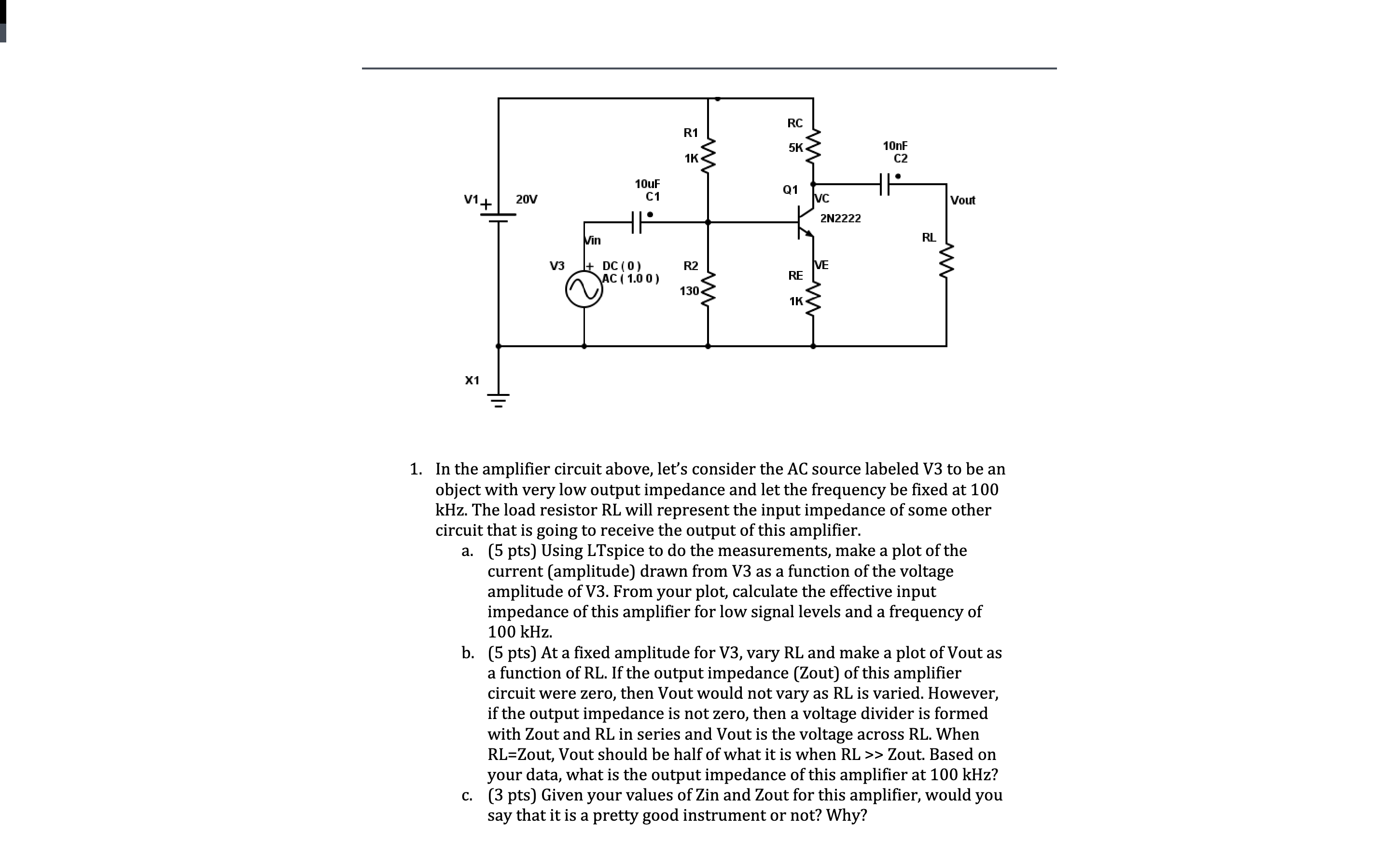
In the amplifier circuit above, let's consider the AC source labeled V to be an object with very low output impedance and let the frequency be fixed at kHz The load resistor RL will represent the input impedance of some other circuit that is going to receive the output of this amplifier.
a pts Using LTspice to do the measurements, make a plot of the current amplitude drawn from V as a function of the voltage amplitude of V From your plot, calculate the effective input impedance of this amplifier for low signal levels and a frequency of kHz
b pts At a fixed amplitude for V vary RL and make a plot of Vout as a function of RL If the output impedance Zout of this amplifier circuit were zero, then Vout would not vary as RL is varied. However, if the output impedance is not zero, then a voltage divider is formed with Zout and RL in series and Vout is the voltage across RL When RLZout, Vout should be half of what it is when RL Zout. Based on your data, what is the output impedance of this amplifier at kHz
c pts Given your values of Zin and Zout for this amplifier, would you say that it is a pretty good instrument or not? Why?
Step by Step Solution
There are 3 Steps involved in it
1 Expert Approved Answer
Step: 1 Unlock

Question Has Been Solved by an Expert!
Get step-by-step solutions from verified subject matter experts
Step: 2 Unlock
Step: 3 Unlock