

Question: 1. Objective: For this lab, it is necessary to design a code to finish two unsigned number addition and display the result in the 7-segment
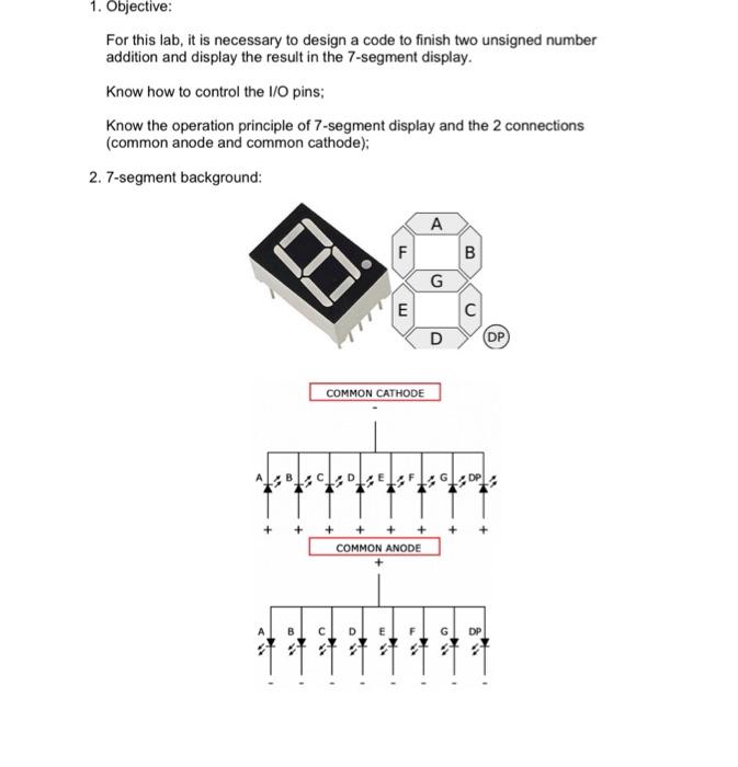
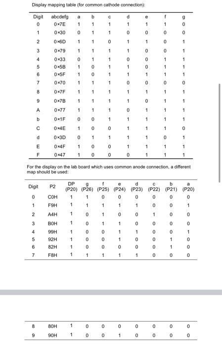
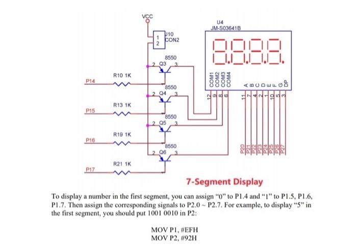
1. Objective: For this lab, it is necessary to design a code to finish two unsigned number addition and display the result in the 7-segment display. know how to control the I/O pins; Know the operation principle of 7-segment display and the 2 connections (common anode and common cathode): 2. 7-segment background: A F 00 G E c D DP COMMON CATHODE DEF + + + COMMON ANODE m 1.9 Display mapping table for common cathode connection); a b d e Digit 0 1 abcdefg 0x7E f 1 g 0 1 1 1 1 1 0 1 1 0 0 0 0 2 1 1 0 1 1 0 1 3 1 1 1 0 0 1 4 5 6 0x30 06D 0x79 0x33 0x5B 0x5F 0x70 0 1 1 1 1 0 0 1 1 1 0 1 1 0 0 1 1 1 1 1 1 1 7 1 1 1 0 0 0 0 8 OK7F 1 1 1 1 1 1 1 9 0x7B 1 1 1 1 0 1 1 0x77 1 1 1 0 1 1 1 b 0x1F 0 0 1 1 1 1 1 0x4E 1 0 0 1 1 1 0 d 0x3D 0 1 1 1 1 0 1 0 1 1 1 1 E F 0x4F 0x47 1 1 0 0 0 0 1 1 1 For the display on the lab board which uses common anode connection, a different map should be used: d C b a P2 Digit 0 DP 9 (P20) (P26) 1 (P25) (P24) (P23) (P22) (P21) P20) 1 0 0 0 0 0 COH F9H 1 1 1 1 1 1 0 1 2 A4H 1 0 1 0 0 Oo oo 1 0 0 1 0 1 3 4 5 6 7 BOH 99H 92H 82H FBH 0 0 0 1 0 0 0 1 1 1 1 0 1 0 1 1 0 0 0 0 0 0 1 1 0 0 1 0 0 0 1 1 1 1 0 0 8 1 0 0 0 0 0 0 0 80H 90H 9 1 0 0 1 0 0 0 0 3. Requirement: 3.1) Choose two unsigned numbers and store them in RO, RI (use Banko registers). Add them up and store the result in R2 (LSB), R3 (MSB). 3.2) Calculate the sum of RO and RI: CLRA ADD A, RO ADD A, RI 3.3) The maximum output will be 255+255 - 510, which is 111111110. 3.4) In order to display the result in the 7-segment devices, BINARY to BCD conversion is required. The example code is shown below: BIN2BCD: divide by 100 B,#100 AB R3.A A#10 divide by 10 MOV DIV MOV MOV XCH DIV SWAP ADD MOV END A,B AB A A,B R4A Please modify this program and write a complete program to finish the display. Moreover, you need to check the carrier status to see whether it is "1". If "C" is set, your BCD result should add 2 5 6 respectively. 3.5) Display the result: the 7-segment display is connected as below: 14 JM-S03641B 110 CON2 8550 2 Q3 LI. R10 1K P14 COM COM COM3 COM4
Step by Step Solution
There are 3 Steps involved in it

Get step-by-step solutions from verified subject matter experts