

Question: 1 . Shown below is a larger - scale elevation view of the left end of the continuous concrete beam shown in Figure 1 3
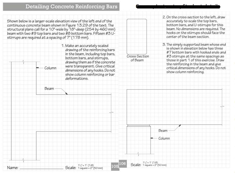
Shown below is a largerscale elevation view of the left end of the
continuous concrete beam shown in Figure of the text. The
structural plans call for a wide by deep by mm
beam with two # top bars and two # bottom bars. Fifteen # U
stirrups are required at a spacing of
Make an accurately scaled
drawing of the reinforcing bars
in the beam, including top bars,
bottom bars, and stirrups,
drawing them as if the concrete
were transparent. Give critical
dimensions of any hooks. Do not
show column reinforcing or bar
deformations.
On the cross section to the left, draw
accurately to scale the top bars.
bottom bars, and Ustirrups for this
beam. No dimensions are required. The
hooks on the stirrups should face the
center of the beam section.
The simply supported beam whose end
is shown in elevation below has three
# bottom bars with hooked ends and
# stirrups at the same spacings as
those in part of this exercise. Draw
the reinforcing in the beam and give
critical dimensions of any hooks. Do not
show column reinforcing.
Step by Step Solution
There are 3 Steps involved in it
1 Expert Approved Answer
Step: 1 Unlock

Question Has Been Solved by an Expert!
Get step-by-step solutions from verified subject matter experts
Step: 2 Unlock
Step: 3 Unlock